DAF 95XF. Manual — part 352
5
MODIFICATIONS TO THE ELECTRICAL INSTALLATION
Modifications to the electrical installation from chassis number 0E477514
4-20
27
1316630/24-29
1
23456789
1
0
1
1
1
2
1
3
1
4
1
5
1
6
1
7
1
8
1
9
2
0
2
1
2
2
2
3
2
4
2
5
2
6
2
7
2
8
2
9
3
0
3
1
3
2
3
3
3
4
3
5
3
6
3
7
3
8
3
9
4
0
4
1
4
2
4
3
4
4
4
5
4
6
4
7
4
8
4
9
5
0
5
1
5
2
5
3
EL000344
3469
1262
1262
3469
3470
3470
1262
D878
1010
1000
1010
1000
E157
15A
23
1
B344
4
M
D853
4/
395
A021
13
10
286
11
286
12
286
18
286
18/401
11
ǹ 0209
5
Modifications to the electrical installation from chassis number 0E477514
MODIFICATIONS TO THE ELECTRICAL INSTALLATION
4-21
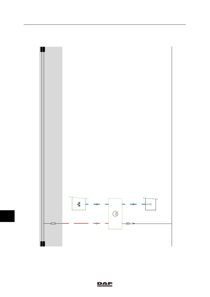
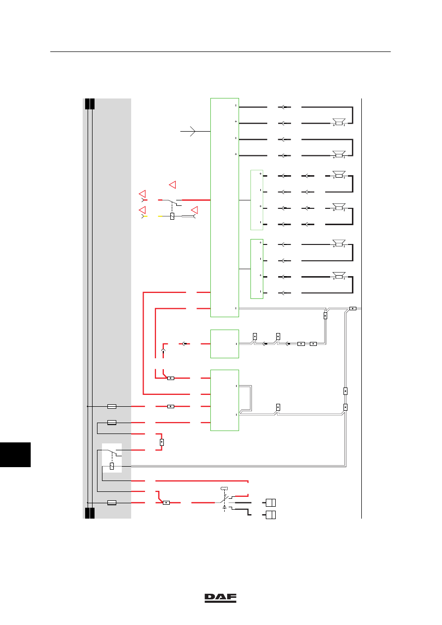
35. CONVERTER/RADIO
The following description of operation and
installation is merely advisory.
Read the manufacturer’s installation
instructions supplied with the radio.
For more information, see chapter 6:
“Connecting the radio”.
The radio is equipped with one antenna
connection and two loudspeaker outputs used to
connect loudspeakers B024 and B025. Two
filters for the loudspeakers can also be
connected to the radio. To each of these filters
(B186 en B187) two loudspeakers can be
connected (B178, B179 and B180 and B181).
The 12V output (pin A4) of the converter (D895)
can also be connected to a CB transmitter
(B026) to provide it with a supply voltage.
VARIANTS
Location
37 Wire No. 2630. This wire should be
connected to one of the search light switch
wires.
41 Wire No. 1108. This wire should be
connected to wire 1108 coming from the
24/12V converter.
11
ǹ 0209
5
MODIFICATIONS TO THE ELECTRICAL INSTALLATION
Modifications to the electrical installation from chassis number 0E477514
4-22
35
1316630/24-29
EL000341
1
23456789
1
0
1
1
1
2
1
3
1
4
1
5
1
6
1
7
1
8
1
9
2
0
2
1
2
2
2
3
2
4
2
5
2
6
2
7
2
8
2
9
3
0
3
1
3
2
3
3
3
4
3
5
3
6
3
7
3
8
3
9
4
0
4
1
4
2
4
3
4
4
4
5
4
6
4
7
4
8
4
9
5
0
5
1
5
2
5
3
1100
1130
1130
1100
1100
1106
1108
1108
4001
4002
1147
1147
1108
1107
1353
1106
1108
1108
1108
1353
4827
4827
4828
4828
4829
4829
4830
4830
4831
4832
4833
4834
4831
4832
4833
4834
4831
4832
4833
4834
1107
1108
2630
4540
4540
4542
4542
4541
4541
4543
4543
15/402
19/402
20/402
3/402
10/403
1/402
1/412
2/412
4/412
6/412
12/403
B178
B179
1
194
2
194
3
194
4
194
B180
B181
G015
85
1
B010
50
1
5
194
6
194
7
194
8
194
17
194
18
194
19
190
20
190
3/427
1/427
B1
A2
B2
3
189
7
190
3
190
12
194
15/403
C539
L2
B186
L2
L1
L1
R2
B187
R2
R1
R1
A4
24V
24V
D895
12V
12V
B026
12V
2
1
7/424
4/424
D878
E037
15A
30
86
85
87A
87
G178
1100
1147
1130
E027
10A
1010
1000
1010
1000
E028
15A
!
!
!
G231
30
85
86
87A
8
7
!
8/424
12
185
B024
13
185
7
187
B025
8
187
12V
1
2V
B185
12V
LL
R
R
11
ǹ 0209
5
Modifications to the electrical installation from chassis number 0E477514
MODIFICATIONS TO THE ELECTRICAL INSTALLATION
4-23
36 AUTOMATIC WINDOWS/ROOF HATCH/CENTRAL DOOR LOCKING
ELECTRIC WINDOW CONTROL, DRIVER’S
SIDE (OPENING)
(Switch in door panel, driver’s side)
If the electric window control switch (C745) is
activated and a connection is made (contacts 2
and 4), relay G030 will be activated through fuse
E044 and switch C745 (wire 4526). As a result,
a supply voltage is applied through fuse E034 to
connection point 2 of the motor (B003). The
other connection point (1) is connected to earth
through relay G031. The motor will start
operating counter-clockwise and the window on
driver’s side will open.
ELECTRIC WINDOW CONTROL, DRIVER’S
SIDE (CLOSING)
(Switch in door panel, driver’s side)
If the electric window control switch (C745) is
activated and a connection is made (contacts 4
and 1), relay G031 will be activated through fuse
E044 and switch C745 (wire 4527). As a result,
a supply voltage is applied through fuse E034 to
connection point 1 of the motor (B003). The
other connection point (2) is connected to earth
through relay G030. The motor will start
operating clockwise and the window on driver’s
side will close.
ELECTRIC WINDOW CONTROL,
CO-DRIVER’S SIDE (OPENING)
(Switch in door panel, driver’s side)
If the electric window control switch (C743) is
activated and a connection is made (contacts 2
and 4), relay G028 will be activated through fuse
E044 and switch C743 (wire 4522). As a result,
a supply voltage is applied through fuse E033 to
connection point 2 of the motor (B004). The
other connection point (1) is connected to earth
through relay G029. The motor will start
operating counter-clockwise and the window on
co-driver’s side will open.
11
ǹ 0209
Нет комментариевНе стесняйтесь поделиться с нами вашим ценным мнением.
Текст