DAF 95XF. Manual — part 228
5
Troubleshooting
DIAGNOSIS
2-3
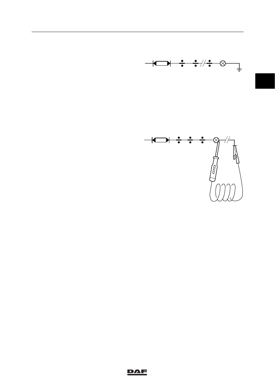
2.2 OPEN CIRCUITS
Suppose a consumer is not functioning. The
fault may then be in the consumer itself, or the
wiring may be interrupted.
First switch on the consumer and check for
voltage with the test lamp. If no voltage is
present, first check whether the fuse is still
intact.
If there is voltage at the fuse, the wiring must be
checked again from the fuse to the consumer.
Every wiring connection must be checked.
If there is no voltage at one of these wiring
connections, the interruption is between this
connection and the connection checked
second-last.
If voltage was found at the consumer, there is
still the possibility of an interruption in the wiring
from the negative terminal of the consumer to
earth. This can be checked with a test lamp.
Make sure the circuit concerned is connected
up.
Connect one end of the test lamp to earth and
the other end to the negative (-) terminal of the
component to be checked.
If the test lamp starts burning, the earth
connection of the component is interrupted. If
the test lamp does not come on, the earth
connection of the component will in most cases
be in good order.
If the positive and negative connections are both
in good order, the consumer is defective and
must be replaced.
W 5 03 015
W 5 03 016
1
ǹ 9711
5
DIAGNOSIS
Troubleshooting
2-4
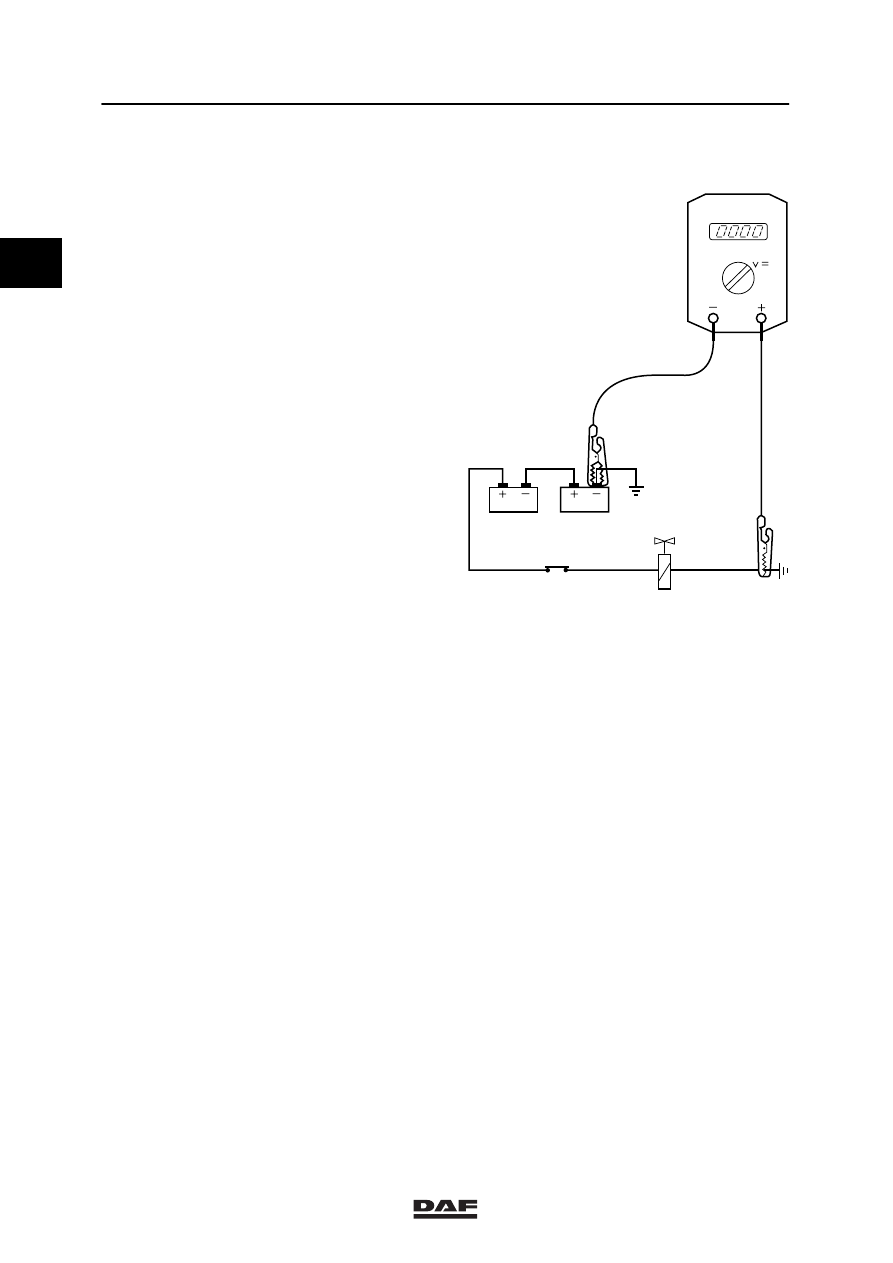
2.3 EARTHING PROBLEMS
Problems with the earth connections are mostly
caused by corrosion on the contact surfaces of
electrical connections.
Earthing problems can only be traced with a
(preferably digital) multimeter. Digital, because
this kind of problem usually involves only a few
volts and the readings of an analog meter are
not precise enough for this purpose.
To establish whether a certain earthing point has
a good earth connection, measure with a
voltmeter between the battery negative pole and
the earthing point in question.
Now switch on as many consumers as possible.
If there is a correct earth connection, no voltage
should be found.
In practice, however, a loss of approx. 0,5V will
often be measured.
If the reading is higher, the earth connection
must be checked carefully.
In this way the earth connections of all the
consumers can be checked and measured.
W 5 03 014
1
ǹ 9711
5
Contents
COMPONENTS
1
CONTENTS
Page
Date
1.
GENERAL
1-1
9811
. . . . . . . . . . . . . . . . . . . . . . . . . . . . . . . . . . . . . . . . . . . . . . . . . . . . . . . . . . . .
. . . . . .
1.1
Multimeter
1-1
9811
. . . . . . . . . . . . . . . . . . . . . . . . . . . . . . . . . . . . . . . . . . . . . . . . . . . . . . .
. . . . . .
1.2
Measuring signals with the multimeter
1-4
9811
. . . . . . . . . . . . . . . . . . . . . . . . . . . . . . .
. . . . . .
2.
DESCRIPTION OF COMPONENTS
2-1
9811
. . . . . . . . . . . . . . . . . . . . . . . . . . . . . . . . . . . . . .
. . . . . .
2.1
Engine speed and vehicle speed sensors
2-1
9811
. . . . . . . . . . . . . . . . . . . . . . . . . . . .
. . . . . .
2.2
Temperature sensors
2-3
9811
. . . . . . . . . . . . . . . . . . . . . . . . . . . . . . . . . . . . . . . . . . . . . .
. . . . . .
2.3
Fluid-level sensors
2-4
9811
. . . . . . . . . . . . . . . . . . . . . . . . . . . . . . . . . . . . . . . . . . . . . . . .
. . . . . .
2.4
Pressure sensors
2-5
9811
. . . . . . . . . . . . . . . . . . . . . . . . . . . . . . . . . . . . . . . . . . . . . . . . .
. . . . . .
2.5
Proximity sensors
2-6
9811
. . . . . . . . . . . . . . . . . . . . . . . . . . . . . . . . . . . . . . . . . . . . . . . . .
. . . . . .
3.
INSPECTION AND ADJUSTMENT
3-1
9811
. . . . . . . . . . . . . . . . . . . . . . . . . . . . . . . . . . . . . . .
. . . . . .
3.1
Checking electrical systems
3-1
9811
. . . . . . . . . . . . . . . . . . . . . . . . . . . . . . . . . . . . . . . .
. . . . . .
4.
REMOVAL AND INSTALLATION
4-1
9811
. . . . . . . . . . . . . . . . . . . . . . . . . . . . . . . . . . . . . . . .
. . . . . .
4.1
Removing and installing contacts from connectors
4-1
9811
. . . . . . . . . . . . . . . . . . . . .
. . . . . .
4.2
Installing contact units on electrical wires
4-3
9811
. . . . . . . . . . . . . . . . . . . . . . . . . . . . .
. . . . . .
4.3
Removal and installation of contact units of 39-pin floor connector
4-5
9811
. . . . . . .
. . . . . .
4.4
Removal and installation of contact units of connectors
with single contact lock
4-7
9811
. . . . . . . . . . . . . . . . . . . . . . . . . . . . . . . . . . . . . . . . . . . .
. . . . . .
4.5
Removal and installation of contact units of connectors
with additional contact lock
4-7
9811
. . . . . . . . . . . . . . . . . . . . . . . . . . . . . . . . . . . . . . . . .
. . . . . .
2
ǹ 9811
5
COMPONENTS
Contents
2
2
ǹ 9811
Нет комментариевНе стесняйтесь поделиться с нами вашим ценным мнением.
Текст