DAF 95XF. Manual — part 468
3
PNEUMATIC GEARBOX COMPONENTS
General
1-4
Operating the shift-down safety
N
V
1
21
22
1
22
21
GV
GP
H
L
H
L
H
L
4
1
21
22
V300118
1
5
4
3
26
H
L
25
2
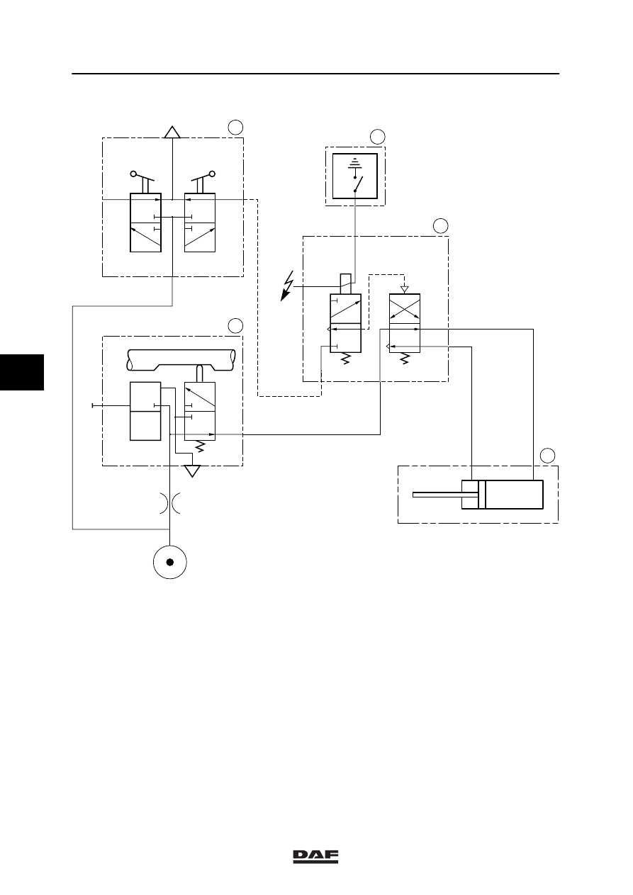
The following applies to pneumatic diagram
V300118
-
Vehicle contact switched off
-
Gearbox in neutral
1.
Neutral position valve
2.
Gear engaging cylinder high/low group
3.
Shift-down safety valve
4.
Electronic unit for CTE
5.
Gear lever shifting valve
L.
Position low auxiliary gearbox
H.
Position high auxiliary gearbox
N.
Gearbox selector shaft in neutral
V.
Gearbox selector shaft engaged
5
ǹ 0002
3
General
PNEUMATIC GEARBOX COMPONENTS
1-5
If the vehicle speed exceeds a particular value
(frequency value), the electronic unit for CTE (4)
interrupts the connection between the
shift-down safety valve (3) and the earth.
Regardless of any pneumatic activation of the
gear lever shifting valve (5), it is now no longer
possible to shift down to the lower group.
Note:
The air supply to the shift-down safety valve (3)
is only available when the gear lever, and hence
also the neutral position valve, are in the neutral
position (N).
5
ǹ 0002
3
PNEUMATIC GEARBOX COMPONENTS
General
1-6
1.3 LOCATION OF THE GATE SAFETY COMPONENTS
1.
Neutral position valve
At the side of the gearbox cover.
2.
Gate safety valve
At the left-hand or right-hand side of the
gearbox (depending on the vehicle type).
3.
Locking cylinder
At the rear of the gearbox cover.
V300140
V300006
V300002
5
ǹ 0002

3
General
PNEUMATIC GEARBOX COMPONENTS
1-7
4.
Electronic unit for gate safety
In the central cabinet on the co-driver’s
side.
5.
CTE-3
In the central cabinet on the co-driver’s
side.
6.
Low-gear switch
Located at the rear of the gearbox.
V300167
V300168
V300005
5
ǹ 0002
Нет комментариевНе стесняйтесь поделиться с нами вашим ценным мнением.
Текст