DAF 95XF. Manual — part 136
6
Inspection and adjustment
BRAKE COMPONENTS
1-27
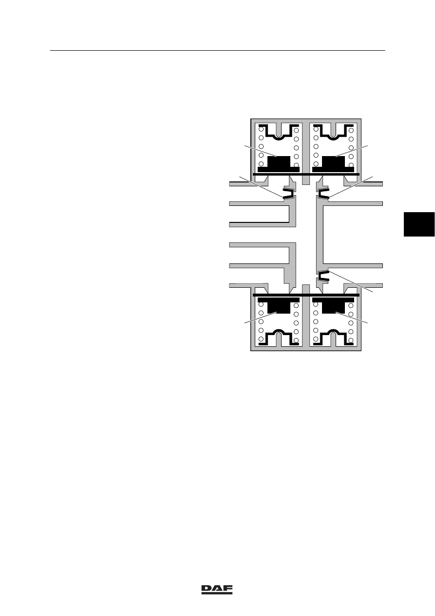
1.15 INSPECTION FOUR-CIRCUIT SAFETY VALVE
Version without circuit 3 reverse flow
function
Inspecting circuits 1, 2 and 4
1.
Lower the pressure in the system to 0 bar.
2.
Connect pressure gauges to circuits 2
and 4.
3.
Simulate a fault in circuit 1 of the service
brake circuit (by disconnecting the line from
the four-circuit safety valve).
4.
Pressurise the other circuits using the
compressor (engine speed approx.
1000 rpm).
5.
The pressure in the intact circuits should
now increase to at least 6.5 bar (to be read
off the gauges).
6.
Switch off the engine. The pressure in the
intact circuits should not fall below the
specified closing pressure, see main group
“Technical data”.
7.
Check the other circuits in the same way.
Checking circuit 3
1.
Lower the pressure in the system to 0 bar.
2.
Connect pressure gauges to circuits 1
and 3.
3.
Pressurise the circuits using the
compressor (engine speed approx.
1000 rpm).
4.
At a pressure of 7.5 bar in circuit 1, the
pressure gauge on circuit 3 should start to
rise.
5.
Switch off the engine and vent a circuit. The
pressure in circuit 3 may not fall below the
specified closing pressure, see main group
“Technical data”.
21
23
22
24
1
a
a
b
5
8
6
9
10
11
7
R600044
4
ǹ 0006
6
BRAKE COMPONENTS
Inspection and adjustment
1-28
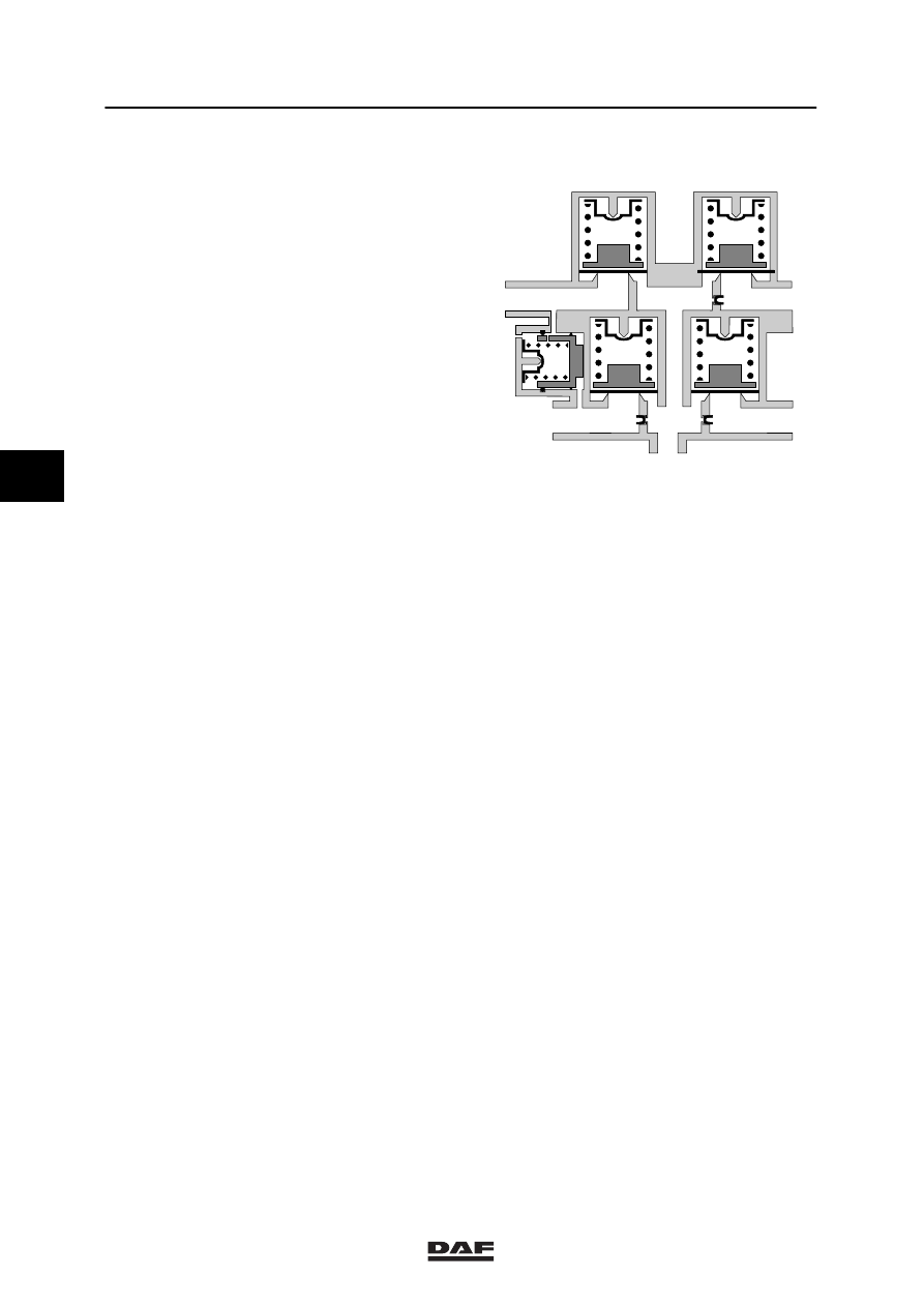
Version with circuit 3 reverse flow function
Inspecting circuits 1, 2 and 4
1.
Lower the pressure in the system to 0 bar.
2.
Connect pressure gauges to circuits 1
and 4.
3.
Simulate a fault in circuit 2 of the service
brake circuit (by disconnecting the line from
the four-circuit safety valve).
4.
Pressurise the other circuits using the
compressor (engine speed approx.
1000 rpm).
5.
The pressure in the intact circuits should
now increase to at least 6.5 bar (to be read
off the gauges).
6.
Switch off the engine. The pressure in the
intact circuits should not fall below the
specified closing pressure, see main group
“Technical data”.
7.
Carry out similar checks with a fault in
circuit 3, and then in circuit 4.
Checking circuit 3
1.
Lower the pressure in the system to 0 bar.
2.
Connect pressure gauges to circuits
1 and 3.
3.
Pressurise the circuits using the
compressor (engine speed approx.
1000 rpm).
4.
At a pressure of 7.5 bar in circuit 1, the
pressure gauge on circuit 3 should start to
rise.
5.
Switch off the engine and vent a circuit. The
pressure in circuit 3 may not fall below the
specified closing pressure, see main group
“Technical data”.
23
24
22
21
1
3
R600336
4
ǹ 0006
6
Inspection and adjustment
BRAKE COMPONENTS
1-29
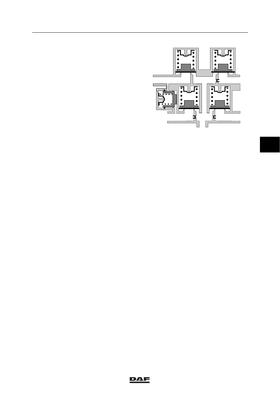
Checking circuit 3 reverse flow function
1.
Connect pressure gauges to circuits
1 and 3.
2.
Pressurise the circuits using the
compressor (engine speed approx.
1000 rpm).
3.
Switch off the engine and lower the
pressure in circuit 1. When the pressure
drops below 4 bar, circuit 3 will slowly be
vented via the exhaust. The pressure
gauge reading on circuit 3 will drop to 0 bar.
23
24
22
21
1
3
R600336
4
ǹ 0006
6
BRAKE COMPONENTS
Inspection and adjustment
1-30
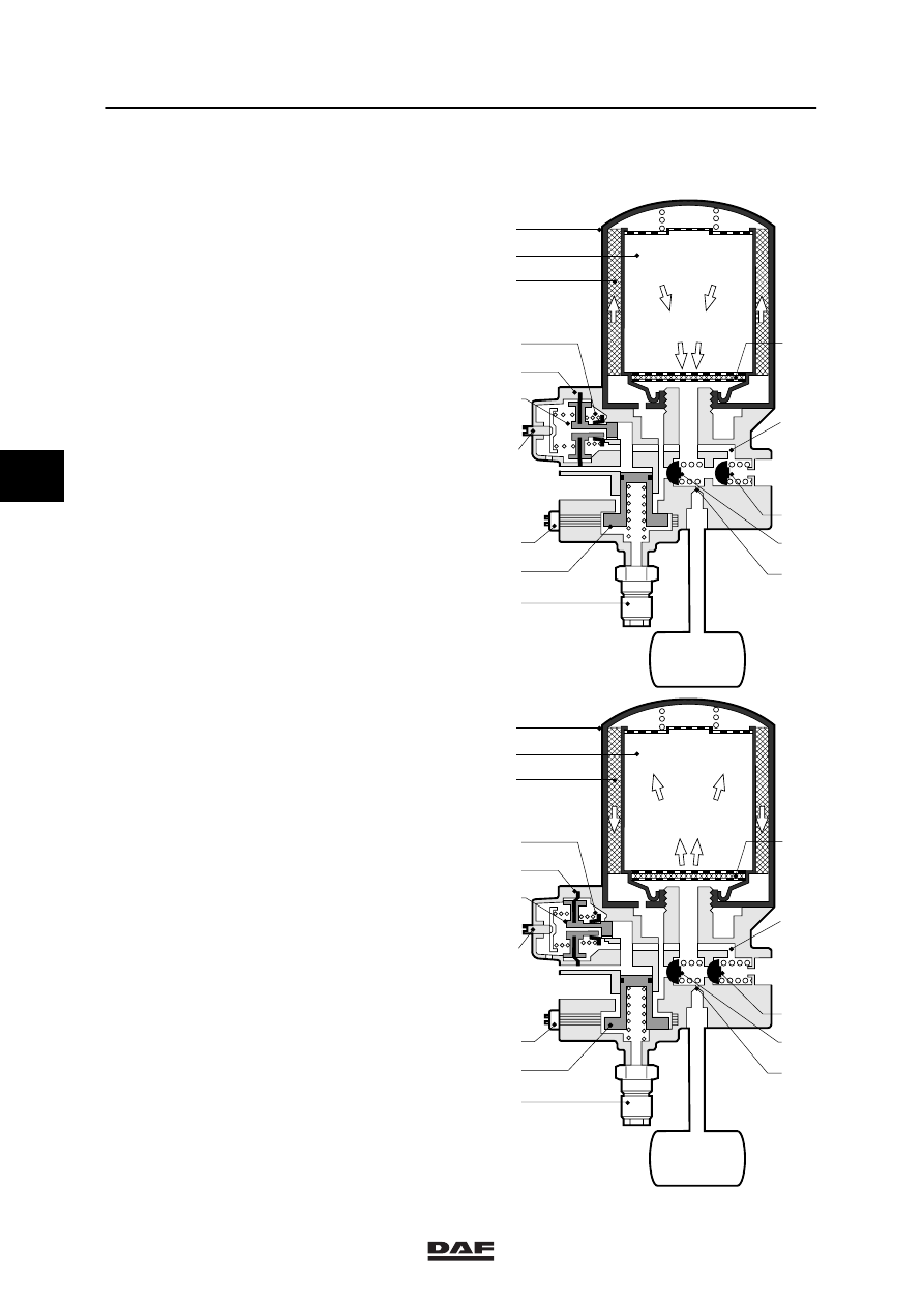
1.16 INSPECTION AND ADJUSTMENT, AIR DRYER
BOSCH design
Adjusting the cut-out pressure
(9.8
ᐔ 0.2 bar)
1.
Adjust the cut-out pressure with adjusting
screw (7).
Checking the regenerative action
of the air dryer
1.
Pressurise the compressed air braking
system (pressure regulator should cut out).
2.
Switch off the engine.
3.
The regeneration air should escape via the
exhaust port of the air dryer, for some time.
1
3
21
22
23
1
23
1
2
3
6
7
8
9
10
12
11
13
14
15
5
4
3
21
22
1
2
3
6
7
8
9
10
12
11
13
14
15
5
4
R600242
4
ǹ 0006
Нет комментариевНе стесняйтесь поделиться с нами вашим ценным мнением.
Текст