DAF 95XF. Manual — part 104
0
6
Contents
TECHNICAL DATA
1
CONTENTS
Page
Date
1. BRAKE SYSTEM
1-1
0006
. . . . . . . . . . . . . . . . . . . . . . . . . . . . . . . . . . . . . . . . . . . . . . . . . . . . . .
. . . . . .
1.1
General
1-1
0006
. . . . . . . . . . . . . . . . . . . . . . . . . . . . . . . . . . . . . . . . . . . . . . . . . . . . . . . . .
. . . . . .
1.2
Tightening torques
1-12
0006
. . . . . . . . . . . . . . . . . . . . . . . . . . . . . . . . . . . . . . . . . . . . . . . .
. . . . .
ǹ 0006
6
TECHNICAL DATA
Contents
2
0
ǹ 0006
0
6
Brake system
TECHNICAL DATA
1-1
3. BRAKE SYSTEM
3.1 GENERAL
Coding of components
All components have been provided with
number codes.
Structure of the code
1
st
digit:
0
Suction connection
1
Energy supply (pressure)
2
Energy outlet
3
Exhaust
4
Control connection
5
Not used
6
Not used
7
Anti-freeze connection
8
Lubricant connection
9
Coolant connection
When one connection performs several
functions, additional first digits will be allocated.
These are separated by a hyphen.
If several connections perform the same
function, a second digit will be added behind the
first.
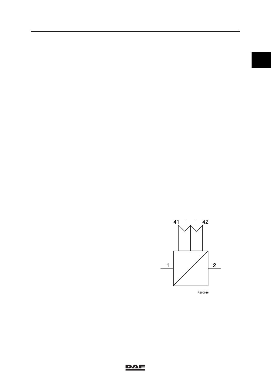
Example
Empty/load relay valve
Meaning:
1
energy supply from air compressor
2
energy discharge to the next component
41
control connection
42
control connection
ǹ 0006
6
TECHNICAL DATA
Brake system
1-2
COMPRESSOR
Design
Make:
Wabco 911 504 500 0
Version:
2-cylinder, water-cooled
Reject sizes Wabco W 911 504 500 0
compressor
Cylinder bore at return point
of first piston ring
75.022 mm
Piston-ring groove height:
first groove
2.035 mm
second groove
2.035 mm
third groove
4.047 mm
Piston-pin bore diameter
15.018 mm
Piston pin diameter
14.992 mm
Piston diameter, measured in longitudinal
direction from piston pin to bottom
of piston skirt
74.962 mm
Piston pin bearing in connecting rod
15.047 mm
Crankshaft bearing diameter, non-driving end
35.070 mm
Crankshaft main bearing, non-driving end
34.963 mm
Diameter of crankshaft local to connecting rod
32.963 mm
Anti-friction bearing at driving end
replace always
SERVICE-BRAKE VALVE
Design
Make:
Knorr MB 4694 ll/14119
Differential pressure between circuits 1 and 2
0.25 - 0.35 bar
Connections
Circuit distribution
circuit 1: rear axle
circuit 2: front axle
Connection 11
circuit 1 supply
Connection 12
circuit 2 supply
Connection 21
circuit 1 braking pressure
Connection 22
circuit 2 braking pressure
ǹ 0006
0
Нет комментариевНе стесняйтесь поделиться с нами вашим ценным мнением.
Текст