DAF 95XF. Manual — part 838
1
CAB SUSPENSION
Removal and installation
4-16
Installing complete cab
1.
Use the lifting beam to place the cab onto
the chassis.
2.
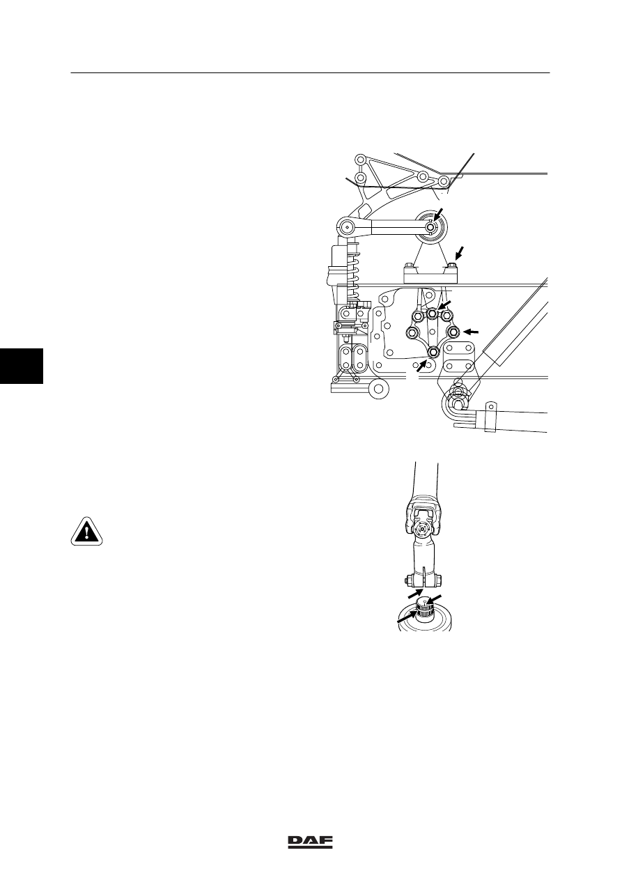
Fit the front left and front right attachment
bolts (J) of the silentblocks.
3.
Attach the spring elements at the bottom.
4.
Remove the lifting yoke.
5.
Attach the lifting cylinder to the cab and
tighten the attachment bolts temporarily to a
tightening torque of 125 Nm.
6.
Tilt the cab slightly forwards and remove the
wooden blocks on the cab locks. Tilt the cab
back again.
7.
Tighten the attachment bolts to the
specified tightening torque, see “Technical
data”.
8.
Tilt the cab forwards.
9.
Tighten the upper attachment bolts of the
lifting cylinder to the specified tightening
torque. See “Technical data”.
K100417
F
G
H
J
K
10. Fit the universal joint on the splines of the
steering shaft or steering box. Line up the
groove (A) in the clutch with mark (B) on the
steering shaft or steering box.
Check that the universal joint is
correctly in place on the steering
shaft or steering box so that the
attachment bolt can be put in the
notch (C).
11. Only fit a new attachment bolt with nut to
the universal joint. Tighten the bolt to the
specified tightening torque, see “Technical
data”.
K1 01 353
A
C
B
5
ᓻ 0209
1
Removal and installation
CAB SUSPENSION
4-17
12. Position the air pipes and connect the
connector blocks.
13. Connect the clutch pipe.
14. Install the air conditioning pipes and secure
them using the attachment nuts.
15. Connect the cable and attach it to the
chassis.
16. Connect the heater hoses to the connector
pipes.
17. Connect the floor connectors and E-gas
connector.
18. In the case of a HGS shift control, connect
the pipes to the coupling piece. Ensure that
no dirt enters the pipes during assembly.
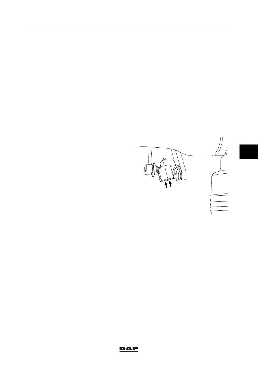
19. In the case of an MGS shift control, fit the
attachment bolts at the bottom of the rocker
strip and tighten them.
20. Install the engine noise insulation
underneath the cab.
21. Tilt the cab back to the driving position.
22. Install the roof hatch rim and the roof hatch
glass.
23. Fit the door rubbers to the left and right.
24. Fill and bleed the clutch main cylinder.
25. Fill the cooling system.
26. Connect the battery.
27. Let the engine idle and top up the cooling
system, if necessary.
28. If applicable, bleed the HGS switch control.
29. If applicable, fill the air conditioning system.
30. Check the lighting and all connections.
V300156
5
ᓻ 0209
1
CAB SUSPENSION
Removal and installation
4-18
5
ᓻ 0209
1
Contents
CAB TILTING MECHANISM
1
CONTENTS
Page
Date
1.
SAFETY INSTRUCTIONS
1-1
0209
. . . . . . . . . . . . . . . . . . . . . . . . . . . . . . . . . . . . . . . . . . . . . . .
. . . . . .
2.
GENERAL
2-1
0209
. . . . . . . . . . . . . . . . . . . . . . . . . . . . . . . . . . . . . . . . . . . . . . . . . . . . . . . . . . . .
. . . . . .
2.1
Operation, tilting mechanism
2-1
0209
. . . . . . . . . . . . . . . . . . . . . . . . . . . . . . . . . . . . . . .
. . . . . .
2.2
Overview drawing, cab tilting pump
2-4
0209
. . . . . . . . . . . . . . . . . . . . . . . . . . . . . . . . . .
. . . . . .
2.3
Overview drawing, lifting cylinder
2-5
0209
. . . . . . . . . . . . . . . . . . . . . . . . . . . . . . . . . . . .
. . . . . .
3.
INSPECTION AND ADJUSTMENT
3-1
0209
. . . . . . . . . . . . . . . . . . . . . . . . . . . . . . . . . . . . . . .
. . . . . .
3.1
Inspecting tilting mechanism
3-1
0209
. . . . . . . . . . . . . . . . . . . . . . . . . . . . . . . . . . . . . . .
. . . . . .
3.2
Inspection and adjustment, pressure limiting valve of
cab tilting pump
3-2
0209
. . . . . . . . . . . . . . . . . . . . . . . . . . . . . . . . . . . . . . . . . . . . . . . . . . .
. . . . . .
4.
REMOVAL AND INSTALLATION
4-1
0209
. . . . . . . . . . . . . . . . . . . . . . . . . . . . . . . . . . . . . . . .
. . . . . .
4.1
Removal and installation, cab tilting pump
4-1
0209
. . . . . . . . . . . . . . . . . . . . . . . . . . . .
. . . . . .
4.2
Removal and installation, lifting cylinder
4-2
0209
. . . . . . . . . . . . . . . . . . . . . . . . . . . . . .
. . . . . .
4.3
Removal and installation, cab tilting pump seals
4-4
0209
. . . . . . . . . . . . . . . . . . . . . . .
. . . . . .
4.4
Removal and installation, two-way valve of cab tilting pump
4-7
0209
. . . . . . . . . . . . .
. . . . . .
5.
DISASSEMBLY AND ASSEMBLY
5-1
0209
. . . . . . . . . . . . . . . . . . . . . . . . . . . . . . . . . . . . . . .
. . . . . .
5.1
Disassembly and assembly, lifting cylinder
5-1
0209
. . . . . . . . . . . . . . . . . . . . . . . . . . .
. . . . . .
6.
DRAINING AND FILLING
6-1
0209
. . . . . . . . . . . . . . . . . . . . . . . . . . . . . . . . . . . . . . . . . . . . . . .
. . . . . .
6.1
Draining, bleeding and refilling tilting mechanism
6-1
0209
. . . . . . . . . . . . . . . . . . . . . .
. . . . . .
6
ᓻ 0209
Нет комментариевНе стесняйтесь поделиться с нами вашим ценным мнением.
Текст