DAF 95XF. Manual — part 305
5
Electrical installation
ELECTRICAL INSTALLATION
2-119
31
1316630/05
EL000137
1234
23/400
10
434
3514
3514
1234
1234
2
434
1234
3514
4697
2/314
1/314
7/314
6/314
5/314
4670
4671
4672
4673
4674
2
182
3461
3461
1
182
3460
3460
4697
4697
11
371
4697
19
434
D529
7
28
4697
5
185
4697
4697
1234
1234
1
371
1234
D805
B7
29
25
336
3514
3514
6
371
D804
16/
334
17/
334
19/
334
D850
3/
455
6/
455
B501
B7
3/
223
A021
5
M
B011
IP
IPS
IP
M
1
23456789
1
0
1
1
1
2
1
3
1
4
1
5
1
6
1
7
1
8
1
9
2
0
2
1
2
2
2
3
2
4
2
5
2
6
2
7
2
8
2
9
3
0
3
1
3
2
3
3
3
4
3
5
3
6
3
7
3
8
3
9
4
0
4
1
4
2
4
3
4
4
4
5
4
6
4
7
4
8
4
9
5
0
5
1
5
2
5
3
D878
1010
1000
1010
1000
E143
15A
1/
305
23/
305
24/
305
12/
305
15/
305
14/
305
2/
305
21/
305
10/
305
11/
305
D597
22/
305
10
ǹ 9711
5
ELECTRICAL INSTALLATION
Electrical installation
2-120
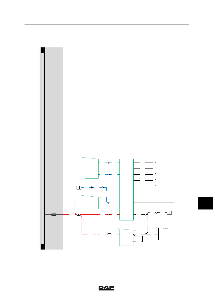
32. ASL-G
SEE THE SYSTEM MANUAL FOR MORE
INFORMATION
10
ǹ 9711
5
Electrical installation
ELECTRICAL INSTALLATION
2-121
32
1316630/05
EL000138
1234
23/400
10
433
3514
3514
1234
3514
4697
4670
4671
B501
B7
3/
223
4697
4697
11
371
4697
19
433
D529
7
28
4697
5
185
4697
4697
D805
B7
29
25
336
3514
3514
6
371
1234
1234
2
433
1234
1234
1
371
1234
2/136
1/136
4788
4788
A021
5
4
D804
16/
334
17/
334
19/
334
8/
135
7/
441
5/
135
6/
135
9/
135
D809
7/
135
8/
441
B174
M
Y
U
D878
1010
1000
1010
1000
E143
15A
1
23456789
1
0
1
1
1
2
1
3
1
4
1
5
1
6
1
7
1
8
1
9
2
0
2
1
2
2
2
3
2
4
2
5
2
6
2
7
2
8
2
9
3
0
3
1
3
2
3
3
3
4
3
5
3
6
3
7
3
8
3
9
4
0
4
1
4
2
4
3
4
4
4
5
4
6
4
7
4
8
4
9
5
0
5
1
5
2
5
3
20
433
4788
10
ǹ 9711
5
ELECTRICAL INSTALLATION
Electrical installation
2-122
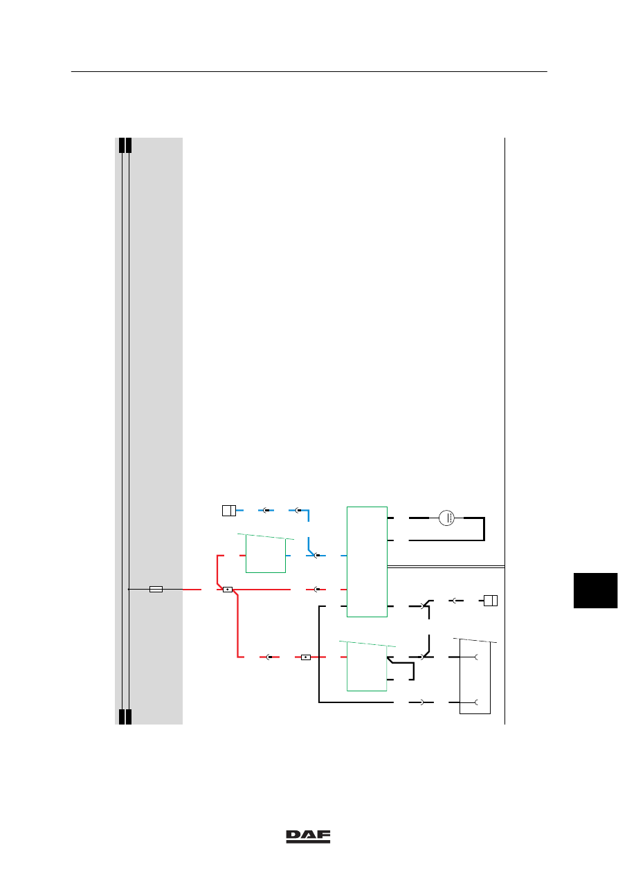
33 HEADLIGHT-HEIGHT ADJUSTMENT
Operation
See also the detailed drawing.
Rear/side marker and parking lights position
A voltage is applied to connection point 2 of the
lighting switch (C622) through fuse E084 and
wire 1101. If a connection is made (contacts 2
and 1) with switch C622, a voltage is applied
through wire 2100 to contact 85 of relay G000
(rear light/ side-light). Once the relay is
activated, a connection is made between points
30 and 87. As a result, a voltage is applied
through relay G000, wire 2101, fuse E117 and
wire 2630 to connection point A of switch C764
(potentiometer for headlight-height adjustment).
Only the LED in the switch will now light up.
Dipped beam position
If a connection is made between contacts 2 and
4 with switch C622, a voltage is applied through
fuse E084, wire 1101, switch C622, wire 2110 to
B129 (left-hand side headlight-height adjustment
motor), connection point 3, B130 (right-hand
side headlight-height adjustment motor) and
C764 (headlight-height adjustment
potentiometer). Depending on the position of
C764 (headlight-height adjustment
potentiometer), the motor in the headlight is
activated. The motor will remain active until an
electric state of balance is achieved. This state
of balance is the actual difference of voltage
between wires 2110 and 4953 of C764, B129
and B130. This difference of voltage should be
equal for all three components.
10
ǹ 9711
Нет комментариевНе стесняйтесь поделиться с нами вашим ценным мнением.
Текст