DAF 95XF. Manual — part 374
5
Electrical system: options and special applications
ELECTRICAL SYSTEM:
OPTIONS AND SPECIAL APPLICATIONS
2-8
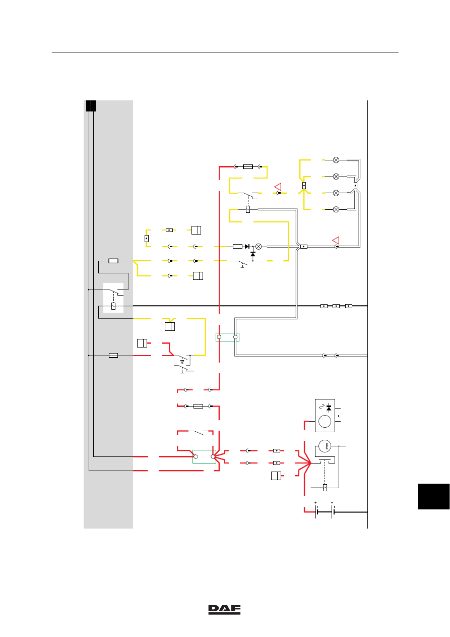
1. ROOF-MOUNTED HIGH-BEAM HEADLIGHTS
A constant voltage is applied through wire 1000
(voltage before contact) and fuse E084 to
connection point 7 of switch C775 (dipped
beam/main beam switch). If the main beam is
switched on (connection between points 7 and
6), a voltage is applied to main beam relay
(G002). Once the relay is activated, a
connection is made between points 30 and 87.
As a result, a voltage is applied through fuse
E007 and wire 2123 to connection point 6 of
roof-mounted high-beam light switch (C813). If
the switch is operated, voltage is applied to
roof-mounted high-beam headlight relay (G299)
as well This relay is energised. Now voltage is
applied through fuse E168 (in overhead box),
wire 1175 (on Pertinax block) (in overhead
box)), and through fuse E188, wire 2134 to
contacts 3 and 1 of roof-mounted high-beam
headlight relay (C299). A voltage is also applied
to the high-beam headlights through wire 2135.
VARIANTS
Location
36, 42
Yw/gr and bl: Involved is a 3-core
cable. Yw/gn has no marking. This is
the earth wire.
Bl is marked 2135.
12
ǹ 9811
5
Electrical system: options and special applications
ELECTRICAL SYSTEM:
OPTIONS AND SPECIAL APPLICATIONS
2-9
5/401
1232300/34
EL000162
1
14/403
1101
A
114
1000
1000
1010
1000
2/233
1/233
G525
G525
G014
1
3
1000
1000
1010
1000
1000
B
114
1000
1000
1000
1000
E168
40A
1175
A2
1
181
30
87
G015
1000
A500
1175
1000
A1
50
B010
M
31
30
G
3
D
B+
D+
A502
C775
7/408
6/408
D853 B15
7
1101
5/402
M
2120
G003
85
10
C166
1
2
C168
1
2
C162
1
2
C164
1
2
2135
2135
2135
2135
2135
2135
G299
3
2
45
1
6
290
2123
2123
2120
4
291
2123
7
C813
10
6
2
6
286
2123
2123
C003
1
10
28/402
13
189
2630
5
291
2630
2630
2630
E117
2
19
2123
2133
1
180
1175
2
180
2
181
E188
15A
1175
1175
2133
Gl/Gn
Bl
6
7
D878
E084
10A
1000
1010
1010
1000
30
86
85
87A
87
G002
2120
2121
E007
10A
1
23456789
1
0
1
1
1
2
1
3
1
4
1
5
1
6
1
7
1
8
1
9
2
0
2
1
2
2
2
3
2
4
2
5
2
6
2
7
2
8
2
9
3
0
3
1
3
2
3
3
3
4
3
5
3
6
3
7
3
8
3
9
4
0
4
1
4
2
4
3
4
4
4
5
4
6
4
7
4
8
4
9
5
0
5
1
5
2
5
3
2134
!
!
12
ǹ 9811
5
Electrical system: options and special applications
ELECTRICAL SYSTEM:
OPTIONS AND SPECIAL APPLICATIONS
2-10
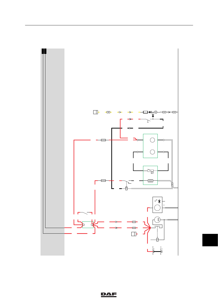
2. FUEL HEATER/WATER SEPARATOR
If the vehicle is switched to contact, a voltage is
applied through wire 1010 and fuse E170 both
to connection point 1 of the electronic unit
(D855) and to the fuel heater/water separator
switch (C747). If this switch is operated, relay
G234 is energised. Now a voltage is applied,
through wire 1000, fuse E171, wire 1179,
contacts 3 and 1 of relay G234 and wire 5051,
to connection point 3 of fuel heater/water
separator sensor (B241).
12
ǹ 9811
5
Electrical system: options and special applications
ELECTRICAL SYSTEM:
OPTIONS AND SPECIAL APPLICATIONS
2-11
A
114
1000
1000
1232300/34
EL000163
2
1000
2/233
1/233
G525
G525
G014
1
3
1000
1000
1010
1000
1000
B
114
1000
1000
1000
1000
30
87
G015
1000
A500
1000
1
23456789
1
0
1
1
1
2
1
3
1
4
1
5
1
6
1
7
1
8
1
9
2
0
2
1
2
2
2
3
2
4
2
5
2
6
2
7
2
8
2
9
3
0
3
1
3
2
3
3
3
4
3
5
3
6
3
7
3
8
3
9
4
0
4
1
4
2
4
3
4
4
4
5
4
6
4
7
4
8
4
9
5
0
5
1
5
2
5
3
D878
1010
1000
1000
1010
50
B010
M
31
30
G
3
D
B+
D+
A502
1010
1000
3
4
5050
gl
zt
2
1
5049
gl
rd
5051
1010
1285
E171
15A
C2
C1
E170
7.5A
B2
B1
7
C747
10
6
2
12
194
2630
5
291
2630
13
189
2630
E117
2
19
2630
1285
1285
1179
5048
5048
1285
1010
5048
5048
3
4
1
2
B241
rdzt
rdzt
rd
rd
D855
ON
DRAIN
G234
3
2
45
1
12
ǹ 9811
Нет комментариевНе стесняйтесь поделиться с нами вашим ценным мнением.
Текст