DAF 95XF. Manual — part 22
0
2
XF engine
TECHNICAL DATA
2-5
Inlet manifold
Attachment bolts
60 Nm
Glow plug attachment nut
55 Nm
Air inlet hose clamps
12 Nm
Turbocharger
Heat shield attachment bolts
30 Nm
(1)
Turbine housing clamp plate attachment nut
15 Nm
Attachment nuts, exhaust manifold
flange/turbocharger
60 Nm
(2)
Elbow on turbocharger
40 Nm
Oil supply pipe banjo bolt
90 Nm
(1)
Secure with Loctite 243
(2)
Apply Copaslip to secure
ǹ 200335
2
TECHNICAL DATA
XF engine
2-6
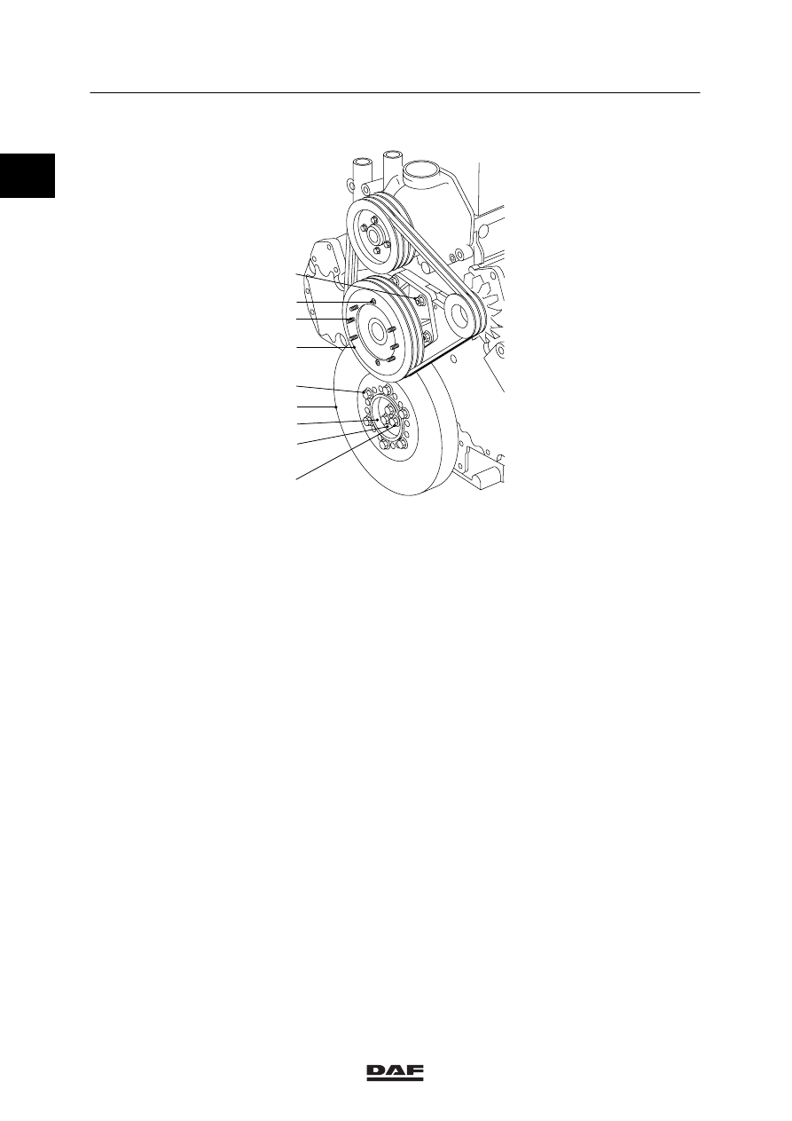
Vibration damper and fan drive
9
7
6
5
4
3
2
1
8
M200945
Vibration damper hub attachment bolts (1) in 4
phases:
1
st
phase, all attachment bolts
100 Nm
(1)
2
nd
phase, all attachment bolts
100 Nm
(1)
3
rd
phase, all attachment bolts
100 Nm
(1)
4
th
phase, all attachment bolts
100 Nm
(1)
Attachment bolts, vibration damper (5)
110 Nm
Attachment nuts, fan drive (8)
60 Nm
Attachment bolts, fan pulley (9)
30 Nm
(2)
Attachment nuts, fan clutch (7)
25 Nm
(2)
(1)
Tighten the attachment bolts evenly
(2)
Secure with Loctite 243
0
ǹ 200335
0
2
XF engine
TECHNICAL DATA
2-7
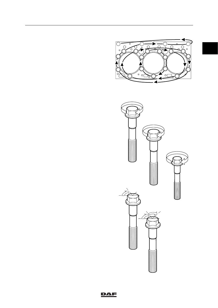
Cylinder head attachment bolts
Cylinder head bolts must only be used once .
So the cylinder head bolts should always be
replaced. The new cylinder head bolts have a
red/brown sealant on the thread.
Note:
-
Because of the sealant used on the cylinder
head bolts, their untightening torque may be
very high!
-
All M16 and M12 threaded holes must be
carefully cleaned with a screw tap before
the bolts are fitted.
-
Once the bolts have been tightened to the
specified torque, the angular displacement
of the M16 bolts must immediately be
started.
-
The sealant cannot be applied later.
Tightening cylinder head attachment bolts
Note:
Apply a drop of oil underneath the bolt heads
(on their abutting surface). Sealant also reduces
the frictional resistance, which means that no oil
must be applied to the thread.
1
st
phase
Tighten M16 in the order
indicated
50 Nm
(1)
2
nd
phase
Tighten M16 in the order
indicated
150 Nm
Tighten M12 in the order
indicated
94 Nm
(1)
3
rd
phase
M16 in the order
indicated
in two steps of
60
_ angular
displacement
(1)
Apply a drop of oil to bolts M16 and M12 on the
abutting surface of the bolt heads.
M200562
16
15
10
5
4
3
9
14
13
12
8
2
1
7
11
17
6
21
18
19
20
M16
50 Nm
I
60
M12
II
III
III
M16
M200563
M16
150 Nm
II
94 Nm
60
M16
ǹ 200335
2
TECHNICAL DATA
XF engine
2-8
Timing gear
Camshaft locking plate attachment bolts
30 Nm
(1)
Attachment bolts, fuel pump drive shaft locking
plate
30 Nm
(1)
Timing case attachment bolts
30 Nm
(1)
Timing cover attachment bolts:
M10 attachment bolts
60 Nm
M8 attachment bolts
25 Nm
Timing cover protection plate attachment bolt
15 Nm
Camshaft gear attachment bolt
425 Nm
(1)
Idler gear attachment bolt
170 Nm
Attachment bolt, fuel pump gear wheel
260 Nm
(1)
Attachment bolt, silencer
30 Nm
Steering pump gear attachment nut
80 Nm
(1)
Steering pump intake pipe banjo bolt
90 Nm
Steering pump delivery pipe banjo bolt
40 Nm
Compressor gear attachment nut
120 Nm
(1)
Secure with Loctite 243
0
ǹ 200335
Нет комментариевНе стесняйтесь поделиться с нами вашим ценным мнением.
Текст