DAF 95XF. Manual — part 259
5
Location of connectors
LOCATION OF CONNECTORS
1-1
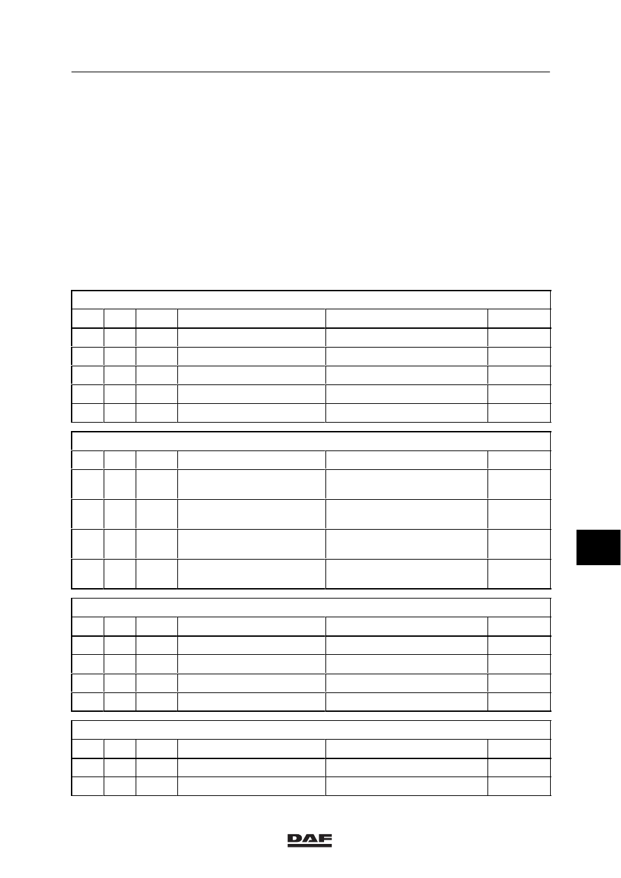
1. LOCATION OF CONNECTORS
1.1 OVERVIEW OF CONNECTORS
Column 1 =
Coding of connectors
Column 2 =
Number of connection points
on connector
Column 3 =
Colour of the connector
Column 4 =
Description of the connector,
if applicable
Column 5 =
Location of the connector on
the vehicle
Column 6 =
Page-number reference (see
“Illustrations of connector
locations”)
Connectors on printed circuit central box (D878)
1
2
3
4
5
6
400
35
Grey
A connector
On printed circuit, central box
1-11
401
35
Black
B connector
On printed circuit, central box
1-11
402
35
Grey
C connector
On printed circuit, central box
1-11
403
35
Black
D connector
On printed circuit, central box
1-11
233
2
Black
Before and after contact
On printed circuit, central box
1-11
Connectors on instrument panel (D852)
1
2
3
4
5
6
200
20
White
C connector
At the back of the instrument
panel
1-9
201
20
Black
B connector
At the back of the instrument
panel
1-9
202
20
Red
A connector
At the back of the instrument
panel
1-9
239
2
Brown
D connector
At the back of the instrument
panel
1-9
Connectors on tachograph (B501)
1
2
3
4
5
6
223
8
White
A connector
At the back of the tachograph
1-9
224
8
Red
C connector
At the back of the tachograph
1-9
225
8
Brown
D connector
At the back of the tachograph
1-9
271
8
Yellow
B connector
At the back of the tachograph
1-9
Connectors on CWS panel (D853)
1
2
3
4
5
6
395
21
Black
A connector
On CWS panel
1-10
396
15
Black
B connector
On CWS panel
1-10
9
ǹ 9711
5
LOCATION OF CONNECTORS
Location of connectors
1-2
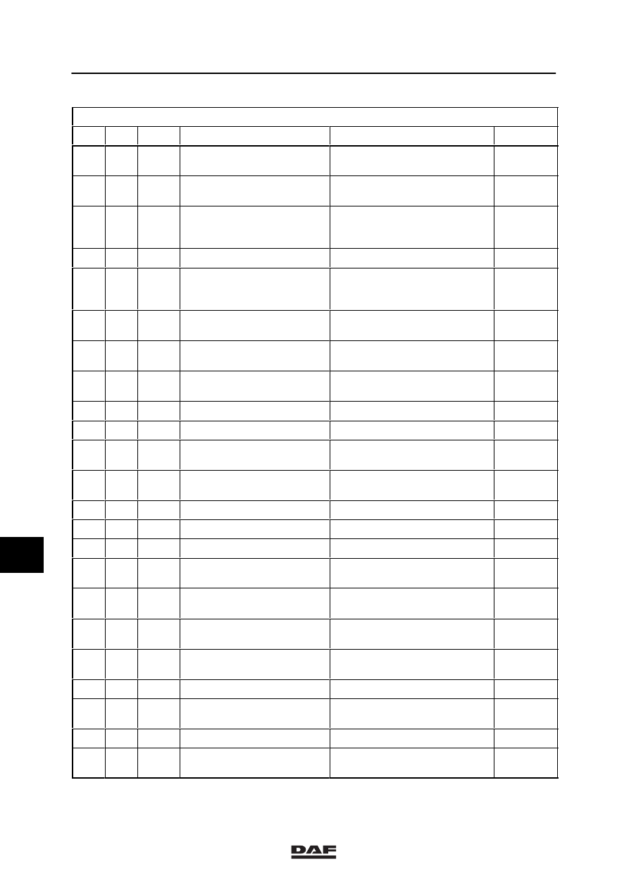
Other connectors
1
2
3
4
5
6
114
39
Red
Engine wiring
Behind the bulkhead on the
co-driver’s side
1-12
115
39
Black
Chassis wiring
Behind the bulkhead on the
co-driver’s side
1-12
116
7
Black
Lifting gear distribution box
wiring harness
Lifting gear distribution box on
the right side of the chassis,
behind the non-driven axle
1-35
118
8
Black
Gearbox wiring harness
On the gearbox, rear right
1-43
122
6
White
Time relay D503
Lifting gear distribution box on
the right side of the chassis,
behind the non-driven axle
1-35
134
4
Red
Electronic unit for gate
safety
Central box
1-49
135
15
Black
Electronic unit for
Groeneveld speed limiter
Central box
1-26
136
4
Black
Groeneveld speed limiter
regulator motor
Below cab, co-driver’s side
1-26
143
4
Black
Stepwell lighting
Below cab floor, right-hand side
1-47
144
4
Black
Stepwell lighting
Below cab floor, left-hand side
1-47
145
16
Black
Auxiliary heating - Webasto
Behind the bulkhead on the
co-driver’s side
1-12/39
161
3
White
Wiring for end-outline
marker lighting
Overhead cover XC cab
1-46
166
2
Black
Electronic unit - Webasto
Central box
1-39
167
10
Black
Electronic unit - Webasto
Central box
1-39
168
8
Black
Electronic unit - Webasto
Central box
1-39
173
8
Black
Thermostat unit for Webasto
auxiliary heating, Thermo 90
Back panel
1-38/40
175
6
Blue
Connection HGS / Airco
dashboard wiring
Central box, left-hand side
1-13/43
176
21
Blue
Connection dashboard
wiring
Instrument panel
1-14
180
2
Brown
Connection accessories
Behind the bulkhead on the
co-driver’s side
1-50
181
2
Brown
Connection accessories
In overhead box
1-50
182
2
White
Connection Egas - ASC
Below printed circuit, right-hand
side
1-61
183
2
White
Airco sensor
Cab outside, front
1-57
185
21
Black
Door-sill wiring, driver’s side
Below instrument panel,
left-hand side
1-14
9
ǹ 9711
5
Location of connectors
LOCATION OF CONNECTORS
1-3
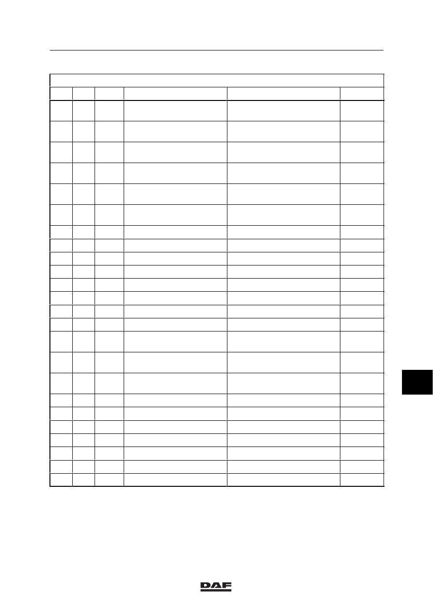
Other connectors
1
2
3
4
5
6
187
12
Blue
Door-sill wiring, co-driver’s
side
Central box, right-hand side
1-13
189
18
Yellow
Overhead-cover wiring XC
cab
Next to instrument panel,
left-hand side
1-14
190
21
Black
Connection overhead-box
wiring XC cab
Overhead cover
1-46
191
6
Blue
Assembly heater-control
panel (XF)
Central box, left-hand side
1-59
192
6
Blue
Assembly heater-control
panel (VF)
Central box, left-hand side
1-60
194
12
Blue
Overhead-cover wiring
Below instrument panel,
left-hand side
1-14
196
9
Black
Door wiring, driver’s side
In door post, driver’s side
1-45
197
6
Blue
Door wiring, driver’s side
In door post, driver’s side
1-45
198
4
White
Door wiring, driver’s side
In door, driver’s side
1-45
199
4
White
Door wiring, driver’s side
In door, driver’s side
1-45
216
16
Black
Diagnosis
Central box, left-hand side
1-18
231
5
Black
Light switch
Instrument panel
1-17
232
55
Black
Electronic unit for CTE
Central box
1-18
251
3
White
Engine brake control switch
On floor at driver’s side
1-19
252
6
White
Wind-screen wiper motor
Behind dashboard, left-hand
side of the heater
1-17
253
12
Black
Electronic unit for automatic
lubrication
Central box
1-42
254
4
Black
Grease pump automatic
lubrication
Below cab floor, right-hand side
1-42
269
14
Black
Thermostat - Eberspächer
Back panel, driver’s side
1-12/23
276
9
Black
Door wiring, co-driver’s side
In door post, co-driver’s side
1-45
277
6
Yellow
Door wiring, co-driver’s side
In door post, co-driver’s side
1-45
278
4
White
Door wiring, co-driver’s side
In door, co-driver’s side
1-45
279
4
White
Door wiring, co-driver’s side
In door, co-driver’s side
1-45
281
18
Blue
Substructure, driver’s side
Below cab, driver’s side
1-15
282
12
Black
Substructure, driver’s side
Below cab, driver’s side
1-15
9
ǹ 9711
5
LOCATION OF CONNECTORS
Location of connectors
1-4
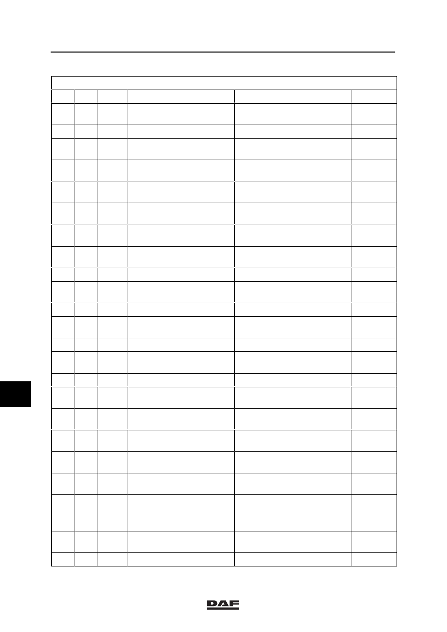
Other connectors
1
2
3
4
5
6
284
12
Black
Chassis substructure
Cable trough below cab,
left-hand side
1-51
285
12
Black
ABS sensors, left-hand side
Below cab, driver’s side
1-55
286
18
Black
Substructure, co-driver’s
side
Central box, above floor
connectors
1-56
288
12
Black
Chassis substructure
Shore on anti-underrun bumper
below the cab, right-hand side
1-58
290
18
Yellow
Connection XL/XH cab
dashboard wiring
Next to instrument panel,
left-hand side
1-14/48
291
21
Black
Connection overhead-box
wiring XL/XH cab
Behind overhead boxes,
left-hand side
1-52
305
25
Black
Electronic unit for VDO
speed limiter
Central box
1-27
307
9
Black
ECAS / E-gas remote
control
Below chair, driver’s side
1-33
313
7
Black
E-gas regulator motor
Below cab, co-driver’s side
1-12
314
7
Black
VDO speed limiter regulator
motor
Below cab, co-driver’s side
1-27
321
39
White
ABS / ECAS wiring
Floor pan
1-12/32/37
328
16
Black
Cable trough ZF-intarder
chassis
Floor pan, co-driver’ s side
1-12/31
333
55
White
Electronic unit for E-gas
Central box
1-19
334
35
Black
Electronic unit for DAF
Cummins interface
Central box
1-22
335
28
Black
Cummins
Engine left
1-24
336
44
Black
Cable harness cab
Cummins
Behind the bulkhead on the
co-driver’s side
1-12/24
338
25
Black
Electronic unit for ZF
intarder
Central box
1-30
340
35
Black
Electronic unit for ECAS-2
(6x2)
Central box
1-32
343
7
Black
Sensor for accelerator
pedal, Cummins
Central box
1-22
344
7
Black
Sensor for accelerator pedal
E-gas
Below cab, driver’s side
1-20
347
12
Black
Cable harness ECAS FTG
In chassis, right-hand side, in
front of
driven axle
1-33
348
16
Black
Cable harness below cab,
air-sprung front axle
Behind the bulkhead on the
co-driver’s side
1-12/32
352
16
Black
Chassis wiring Voith retarder
Floor pan, co-driver’ s side
1-12/29
9
ǹ 9711
Нет комментариевНе стесняйтесь поделиться с нами вашим ценным мнением.
Текст