DAF 95XF. Manual — part 336
5
MODIFICATIONS TO THE ELECTRICAL INSTALLATION
Modifications to the electrical installation from chassis number 0E473500
3-30
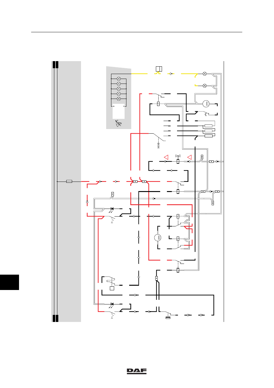
20. HEATER FAN/ AIR-CONDITIONING SYSTEM
A voltage is applied to the heater fan switch
(C588) through the heater fan fuse (E031).
Depending on the position of this switch, the fan
will start operating.
The switch has five (5) positions:
Off:
Heater fan (B015) off.
Position 1:
Fan at lowest speed setting
(wire 4650), supply of heater
fan (B015) through three (3)
resistors.
Position 2:
Fan at somewhat higher
speed setting (wire 4651),
supply of heater fan (B015)
through two (2) resistors.
Position 3:
Heater fan in next to highest
speed setting (wire 4652),
supply of heater fan (B015)
through one (1) resistor.
Position 4:
Heater fan in highest speed
setting (wire 4653), relay
G065 now activated. This
relay connects the supply
(wire 1201) to wire 4654 and
the heater fan. The relay is
only activated in position 4 (full
supply voltage of heater fan
B015).
AIR-CONDITIONING SYSTEM
SHORT DESCRIPTION OF THE
RECIRCULATION VALVE
If switch C802 (air-conditioning recirculation
valve) is activated, a voltage is applied to point 1
of relays G257 and G258. As a result, pin 2 of
recirculation-valve motor B252 is connected to
earth and simultaneously pin 1 of B252 is
connected to the positive voltage. This will
activate motor B252 and close the recirculation
valve.
If C802 is not activated, no voltage is applied to
both relays G257 and G258. As a result, the
direction of flow of the current through motor
B252 is reversed and the recirculation valve will
open.
11
ǹ 0209
5
Modifications to the electrical installation from chassis number 0E473500
MODIFICATIONS TO THE ELECTRICAL INSTALLATION
3-31
SHORT DESCRIPTION OF THE
AIR-CONDITIONING SYSTEM
When the air-conditioning system is engaged
with switch C760, a voltage is applied to relay
G279 through wire 4655 and a voltage to relay
G267 through switch E508 (air-conditioning
compressor temperature switch), E509
(air-conditioning high/low pressure operating
switch) and wire 4657.
As a result, the heater fan (B015) will start
operating in position 1 and the air-conditioning is
activated.
VARIANTS
Location
33 A round 4-pin black connector is attached to
the wiring harness coming from B043
(air-conditioning compressor). This
connector is not provided with a connector
number and is installed at the front (upper
centre) of the engine block.
SEE THE SYSTEM MANUAL FOR MORE
INFORMATION.
11
ǹ 0209
5
MODIFICATIONS TO THE ELECTRICAL INSTALLATION
Modifications to the electrical installation from chassis number 0E473500
3-32
4655
C760
3
2
1
5
4655
4655
3
397
4655
20
1316630/13-23
EL000258
1201
1201
2622
B501
2
2
16/202
2622
2
397
2622
4650
4651
4652
4654
4654
4658
4653
4654
4650
4659
1
2
3
4
5
6
7
8
9
10
11
12
13
14
15
16
17
18
19
20
21
22
23
24
25
26
27
28
29
30
31
32
33
34
35
36
37
38
39
40
41
42
43
44
45
46
47
48
49
50
51
52
53
C053
1
2
C052
1
2
C588
1
4
5
3
2
6
5
3
2
14
B015
M
8
7
E508
3
1
E509
1
2
P
G280
30
86
85
87A
87
2622
1
397
1201
DVB
1201
C802
3
2
1
5
4659
17
376
4659
9
397
4659
1201
1
376
1201
4656
4
397
4656
2
175
4656
4656
16
376
15/401
G279
3
1
24
5
2
1
B043
G267
3
1
24
5
4657
D852
1201
1201
4659
1201
B252
M
1
2
5054
5053
3
54
G257
1
2
3
54
G258
1
2
4657
1201
4657
1201
1201
1201
4655
4650
12
397
1201
5055
14
114
8
397
5055
5055
1201
1201
D
114
4656
1
183
4656
!
!
21
376
D878
1010
1000
1010
1000
E031
15A
5
397
4657
3
175
4657
2
183
4655
11
ǹ 0209
5
Modifications to the electrical installation from chassis number 0E473500
MODIFICATIONS TO THE ELECTRICAL INSTALLATION
3-33
23. ABS/ASC
VARIANTS
Location
24 Connector A004 is only used in the case of
an FA. Connector A005 is used in the case
of an FT.
SEE THE SYSTEM MANUAL FOR MORE
INFORMATION.
11
ǹ 0209
Нет комментариевНе стесняйтесь поделиться с нами вашим ценным мнением.
Текст