DAF LF45, LF55 Series. Manual — part 485
0
7
LF45/55 series
F60 front axle
TECHNICAL DATA
5-3
5.2 TIGHTENING TORQUES
The tightening torques stated in this section are
different from the standard tightening torques
included in the overview of standard tightening
torques. Any other threaded connections that
are not specified must therefore be tightened to
the tightening torque stated in the overview of
standard tightening torques.
When attachment bolts and nuts are to be
replaced, it is important - unless stated
otherwise - that these bolts and nuts are of
exactly the same length and property class as
the ones removed
.
ᓻ 200322
7
TECHNICAL DATA
F60 front axle
LF45/55 series
5-4
S7 00 698
;;;
;;;
;;;
;;;
;;;
;;;
;;
;;
;;
;;
;;
;;
;;
;;
;;
;;
;;;
;;;
;;;
;;;
;;;
;;
;
;;
;;
;;
;;;
;;;
;;
;
;;
;
;;;
;;
;
;
;
;;
;;
;;
;
;
;
;
;;
;;
;
;
;;
;;
;;;;
;;;;
;;;;
;;;;
;;;;
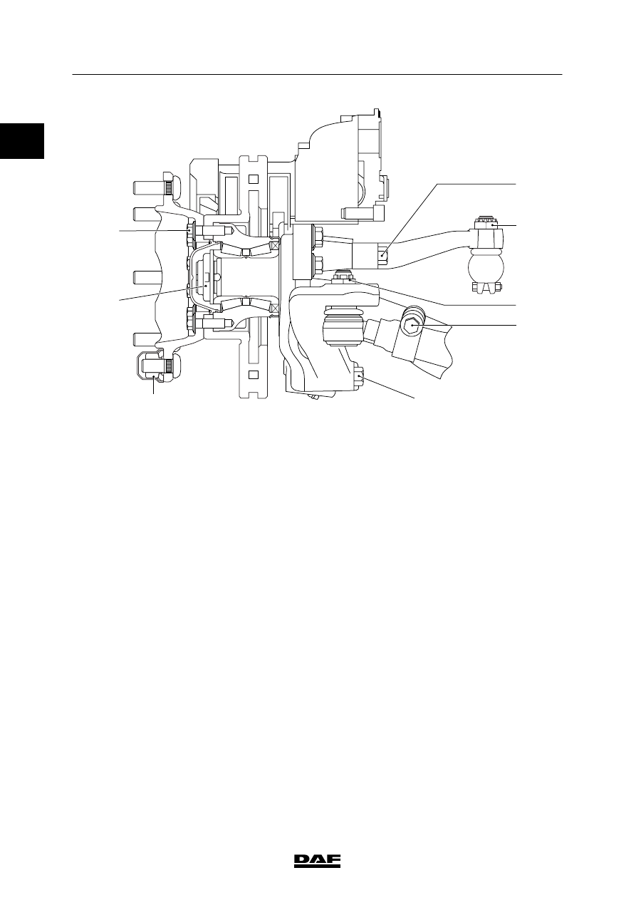
A
C
D
B
E
G
H
F
A.
Steering-rod arm attachment bolt
370
ᐔ 35 Nm
(1)
B.
Steering rod castle nut
220 Nm
(2)
C.
Track rod castle nut
280
ᐔ 25 Nm
(2)
D.
Clamping bracket attachment bolt
80
ᐔ 10 Nm
(3)
E.
Track-rod arm attachment bolt
420
ᐔ 40 Nm
(1)
F.
Wheel nut (M20 x 1.5)
485
ᐔ 35 Nm
(4)
G.
Hub nut
-
1
st
phase
300 Nm
(5)
-
2
nd
phase
turn the hub through 10 rotations
(6)
-
3
rd
phase
350 Nm
-
4
th
phase
turn the hub through 10 rotations
(6)
-
5
th
phase
685
ᐔ 65 Nm
H.
Wheel hub attachment bolt
210
ᐔ 40 Nm
(1)
Apply Loctite 243 to the attachment bolt.
(2)
Tighten until the split pin fits (max. 60
_).
(3)
Fit new self-locking nut.
(4)
Retighten after 100 km. If new wheel bolts have been
fitted, the wheels need additional retightening after
500 km.
(5)
Fit new hub nut.
(6)
Rotate the hub at a speed of approx. 40 rpm.
0
ᓻ 200322
0
7
LF45/55 series
152N front axle
TECHNICAL DATA
6-1
6. 152N FRONT AXLE
6.1 GENERAL
Axle journal
Anti-corrosion agent
Gleitmo 805
Wheel speed sensor
Anti-corrosion agent
Molykote P37
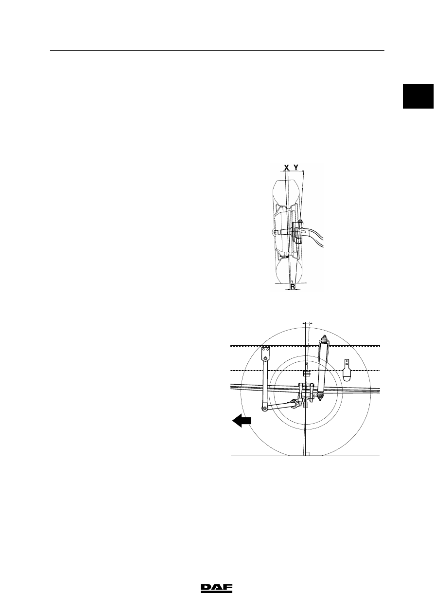
Camber angle and kingpin inclination (KPI)
Camber angle (X) on an
unloaded axle
1
_
King-pin inclination (Y)
7
_30′
S7 00 129
Caster
Z = caster
3
_
Z
S7 00 607
ᓻ 200322
7
TECHNICAL DATA
152N front axle
LF45/55 series
6-2
List of keys that can be supplied for adjusting
caster (Z)
Key angle
W
(1)
L
H
0.5
_
78
155
2.85
1
_
78
155
4.20
1.5
_
78
155
5.55
2
_
78
155
6.91
2.5
_
78
155
8.26
3
_
78
155
9.62
(1)
Spring leaf width
1,5
±0,3
H
±0,3
B
±1
L
±2
20,5
S7 00 107
Wheel deflection
Maximum inner wheel
deflection
50
_
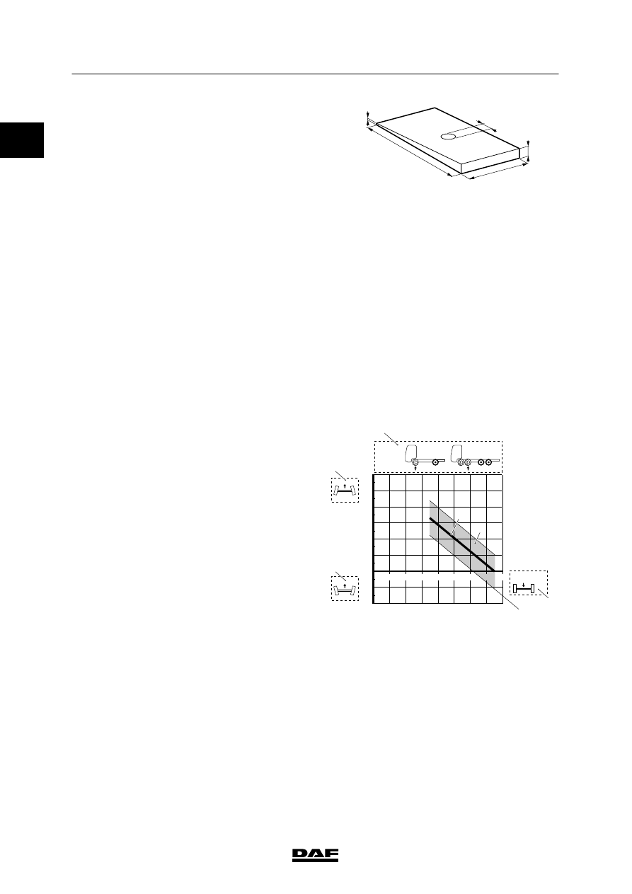
Toe
Toe values are shown in the graph.
Note:
In the graph, the toe has a value of
0.5
ᐔ 1 mm/m toe-in at 75% of the permissible
loading weight. The axle load consists of the
unloaded axle weight + loading weight.
Explanation of graph
1.
At the top of the graph, the axle type and
the axle configuration (1) is shown.
2.
The toe is shown in mm/m on the left-hand
side of the graph. The values above the 0
line show toe-in values, indicated by the
symbol (2).
The values below the 0 line show toe-out
values, indicated by the symbol (3). The
toe-out values are shown as negative
values.
3.
The axle load (4) is shown at the bottom of
the graph.
4.
The permitted toe at any axle load is
indicated by the shaded area (5) in the
graph.
5.
If the measured value lies outside the
shaded area, the toe must be adjusted to
the value indicated by the continuous
line (6).
1
2
3
4
5
6
7
8
0
-1
0,5
-0,5
-1,5
1,5
2,5
3,5
4,5
5,5
-2
2
3
4
5
6
1
mm/m
152 N
x 1000 KG
1
2
3
4
5
6
S7 00 422
0
ᓻ 200322
Нет комментариевНе стесняйтесь поделиться с нами вашим ценным мнением.
Текст