DAF LF45, LF55 Series. Manual — part 622
9
LF45/55 series
Removal and installation
STABILISERS AND TORQUE RODS
2-5
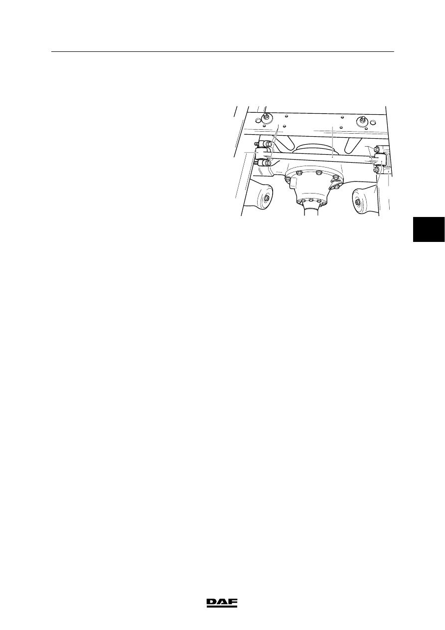
2.3 REMOVAL AND INSTALLATION, TRANSVERSE GUIDE TORQUE ROD, AIR
SPRUNG REAR AXLE LF45
Removal, transverse guide torque rod
1.
Remove the attachment bolts (1) on the
side (2) at which the torque rod (5) is
attached to the rear axle.
2.
Remove the attachment bolts (3) on the
side (4) at which the torque rod (5) and the
attachment bracket (6) are attached to the
chassis.
3.
Remove the torque rod (5) together with the
attachment bracket (6).
Installation, transverse guide torque rod
Caution: on one side of the torque rod, the
mounting rubber is fitted into the eye of the
torque rod at an angle. This side must be fitted
to the rear axle.
1.
Fit the torque rod (5) with the attachment
bolt (6) to the chassis. Hand-tighten the
attachment bolts (3).
2.
Position the other side (2) of the torque rod
(5) on the attachment point of the rear axle
and fit the attachment bolts (1).
3.
Tighten all attachment bolts (1 and 3).
1
2
3
4
6
5
C9 00 403
4
ǹ 0207
9
STABILISERS AND TORQUE RODS
Removal and installation
LF45/55 series
2-6
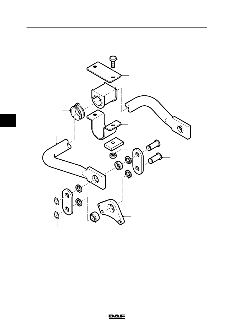
2.4 REMOVAL AND INSTALLATION, AIR-SPRUNG REAR AXLE STABILISER
LF55 13-15 TON GVW
1
2
3
4
6
7
9
12
10
11
13
14
8
5
C9 00 319
Removal, air-sprung rear axle stabiliser bar
LF55 13-15 ton GVW
1.
Remove the attachment bolts (3) and nuts
(8) from the bearing bush covers (6) and
stiffeners (7).
2.
Remove the bearing bush covers (6) from
the stiffeners (7).
4
ǹ 0207
9
LF45/55 series
Removal and installation
STABILISERS AND TORQUE RODS
2-7
3.
Remove the attachment bolts and nuts from
the shackle brackets (12) in the differential.
4.
Remove the stabiliser bar.
Installation, air-sprung rear axle stabiliser
bar LF55 13-15 ton GVW
1.
Check the condition of all the rubbers and
hinge points.
2.
Fit the stabiliser bar (1) under the chassis.
3.
Fit the shackle brackets (12) of the stabiliser
bar in the hinge points on the differential.
4.
Fit the attachment nuts and bolts of the
shackle brackets (12) and tighten them.
5.
Fit the bearing bush cover (6) together with
the stiffeners (7) over the silentblocks (5)
and the retaining plates (4). Tighten the
attachment bolts (3) and nuts (8).
4
ǹ 0207
9
STABILISERS AND TORQUE RODS
Removal and installation
LF45/55 series
2-8
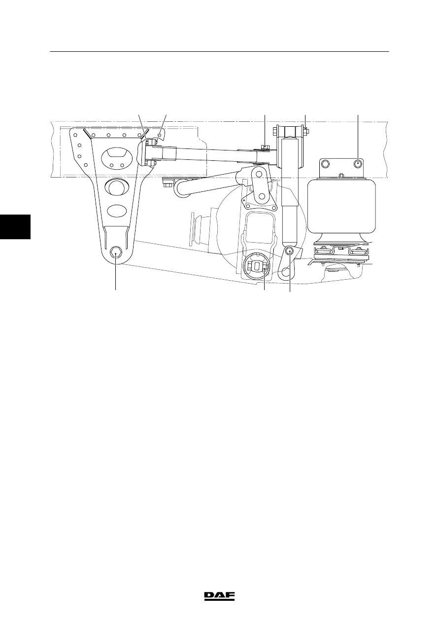
2.5 REMOVAL AND INSTALLATION, TRIANGULAR LINK, AIR-SPRUNG REAR
AXLE LF55 13-15 TON GVW
C9 00 410
1
2
3
4
5
6
7
8
9
10
Removal, triangular link, air-sprung rear axle
LF55 13-15 ton GVW
1.
Detach any valves on the inside of the
chassis that may hinder removal of the
triangular link.
2.
Remove the attachment nut (3) of the
silentblock on the differential.
3.
Remove the attachment bolts (2) and nuts
(1) of the mounting rubbers on the triangle
legs.
4.
Jack up the chassis until the triangle is free
of stress.
5.
Remove the triangle from the differential.
Use a pulley puller of the silentblock does
not come off the attachment pin on the
differential.
4
ǹ 0207
Нет комментариевНе стесняйтесь поделиться с нами вашим ценным мнением.
Текст