DAF LF45, LF55 Series. Manual — part 574
8
LF45/55 series
Removal and installation
SINGLE REAR AXLE 5.10
4-5
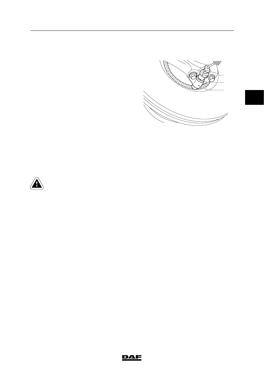
4.5 REMOVAL AND INSTALLATION, WHEEL-SPEED SENSOR
Removing the wheel-speed sensor
1.
Remove the wheel-speed sensor (1) from
the holder (3).
2.
Cut the clamping strips attaching the cable.
3.
Unplug the connector and remove the
wheel-speed sensor.
Installing the wheel-speed sensor
1.
Clean the wheel-speed sensor (1) and the
clamping sleeve (2). If necessary, replace
the clamping sleeve (2).
2.
Apply the specified anti-corrosion agent to
the circumference of the wheel-speed
sensor (1). See main group “Technical
data”.
3.
Fit the wheel-speed sensor (1) in the holder
(3). Press it against the sensor ring
manually.
While the vehicle is being driven, the air gap
between the sensor and the sensor ring is
adjusted automatically.
Never tap the sensor with a
hammer. This may damage both the
sensor and the sensor ring.
4.
Fit the connector and secure the cable with
clamping strips.
5.
Check the ABS system for proper operation.
A8 00 435
2
3
1
2
ᓻ 200313
8
SINGLE REAR AXLE 5.10
Removal and installation
LF45/55 series
4-6
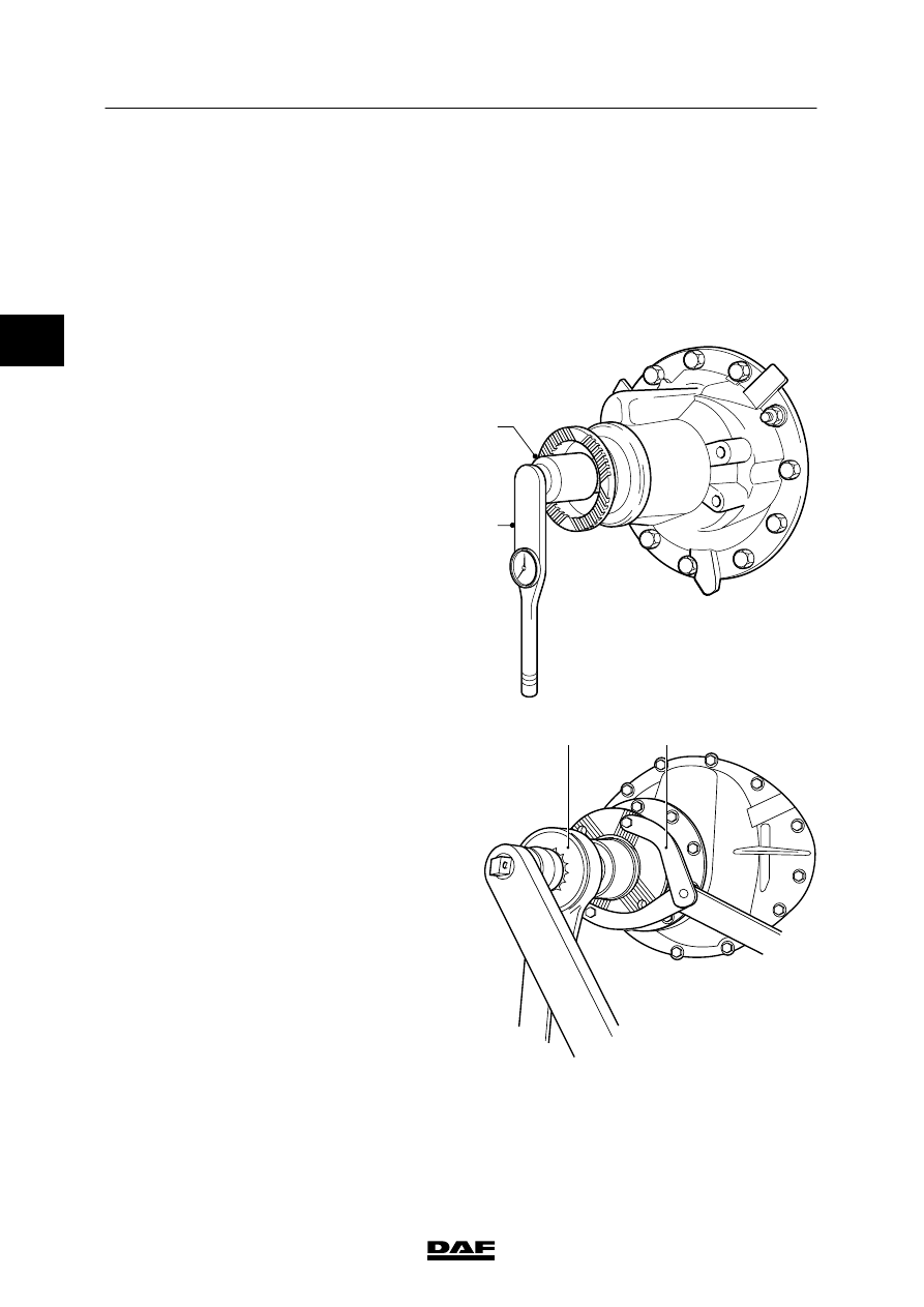
4.6 REMOVAL AND INSTALLATION, DRIVE FLANGE
Removing drive flange
1.
Remove the prop shaft from the drive
flange.
2.
Jack up the rear axle and support it on
stands.
3.
Remove the stub axles.
4.
Determine the pre-load of the pinion
bearings by turning the drive flange nut
using a torque wrench with a dial (2) and a
12-sided socket (1). Write down the
measured slip torque.
A8 00 442
2
1
5.
Fit the special tool (B) (DAF No. 0484977)
on the drive flange to prevent it from
turning. Remove the drive flange nut using
a 12-sided socket and a torque
amplifier (A).
6.
Remove the drive flange. If necessary, use
a puller.
Installing drive flange
1.
Check the dust seal ring of the drive flange.
If required, replace the dust seal ring.
2.
Check the drive flange at the oil-seal
running surface for grooves and/or sharp
edges. If required, replace the drive flange.
3.
Clean the splines of the pinion and drive
flange.
A
B
A8 00 386
ᓻ 200313
2
8
LF45/55 series
Removal and installation
SINGLE REAR AXLE 5.10
4-7
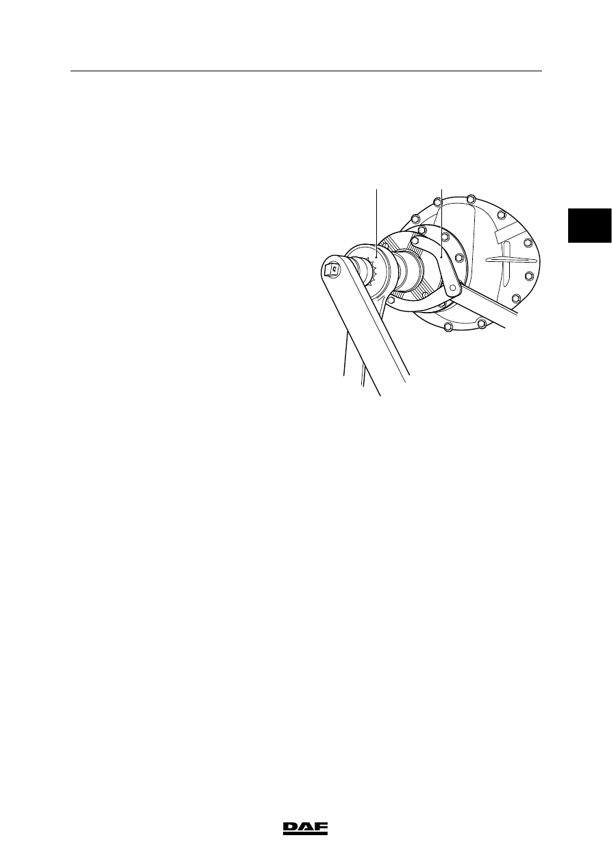
4.
Apply the specified sealant to the splines of
the pinion. See main group “Technical data”.
5.
Fit the drive flange.
6.
Fit a new drive flange nut.
7.
Fit the special tool (3) (DAF No. 0484977)
to the drive flange to prevent it from turning.
Tighten the drive flange nut using a
12-sided socket and a torque amplifier (A)
until no play is noticeable on the pinion.
8.
Turn the drive flange a number of times to
“seat” the pinion bearings.
9.
Tighten the drive flange until the slip torque
of the drive flange nut exceeds the noted
value by 0.4 - 0.6 Nm.
Note:
If the slip torque of the drive flange nut
exceeds the noted value increased by
0.4 - 0.6 Nm, loosen the drive flange nut a
few strokes and repeat the setting
procedure.
10. Fit the stub axles.
11. Fit the prop shaft to the drive flange.
A
B
A8 00 386
2
ᓻ 200313

8
SINGLE REAR AXLE 5.10
Removal and installation
LF45/55 series
4-8
4.7 REMOVAL AND INSTALLATION, PINION OIL SEAL
Removing pinion oil seal
1.
Remove the prop shaft from the drive
flange.
2.
Jack up the rear axle and support it on
stands.
3.
Remove the stub axles.
4.
Determine the pre-load of the pinion
bearings by turning the drive flange nut
using a torque wrench with a dial (2) and a
12-sided socket (1). Write down the
measured slip torque.
A8 00 442
2
1
5.
Fit the special tool (B) (DAF No. 0484977)
on the drive flange to prevent it from
turning. Remove the drive flange nut using
a 12-sided socket and a torque
amplifier (A).
6.
Remove the drive flange. If necessary, use
a puller.
A
B
A8 00 386
2
ᓻ 200313
Нет комментариевНе стесняйтесь поделиться с нами вашим ценным мнением.
Текст