DAF LF45, LF55 Series. Manual — part 281

©
200416
4-1
BE Engine inlet/exhaust system
TECHNICAL DATA
ΛΦ45/55 series
4
0
4. BE ENGINE INLET/EXHAUST SYSTEM
4.1 GENERAL
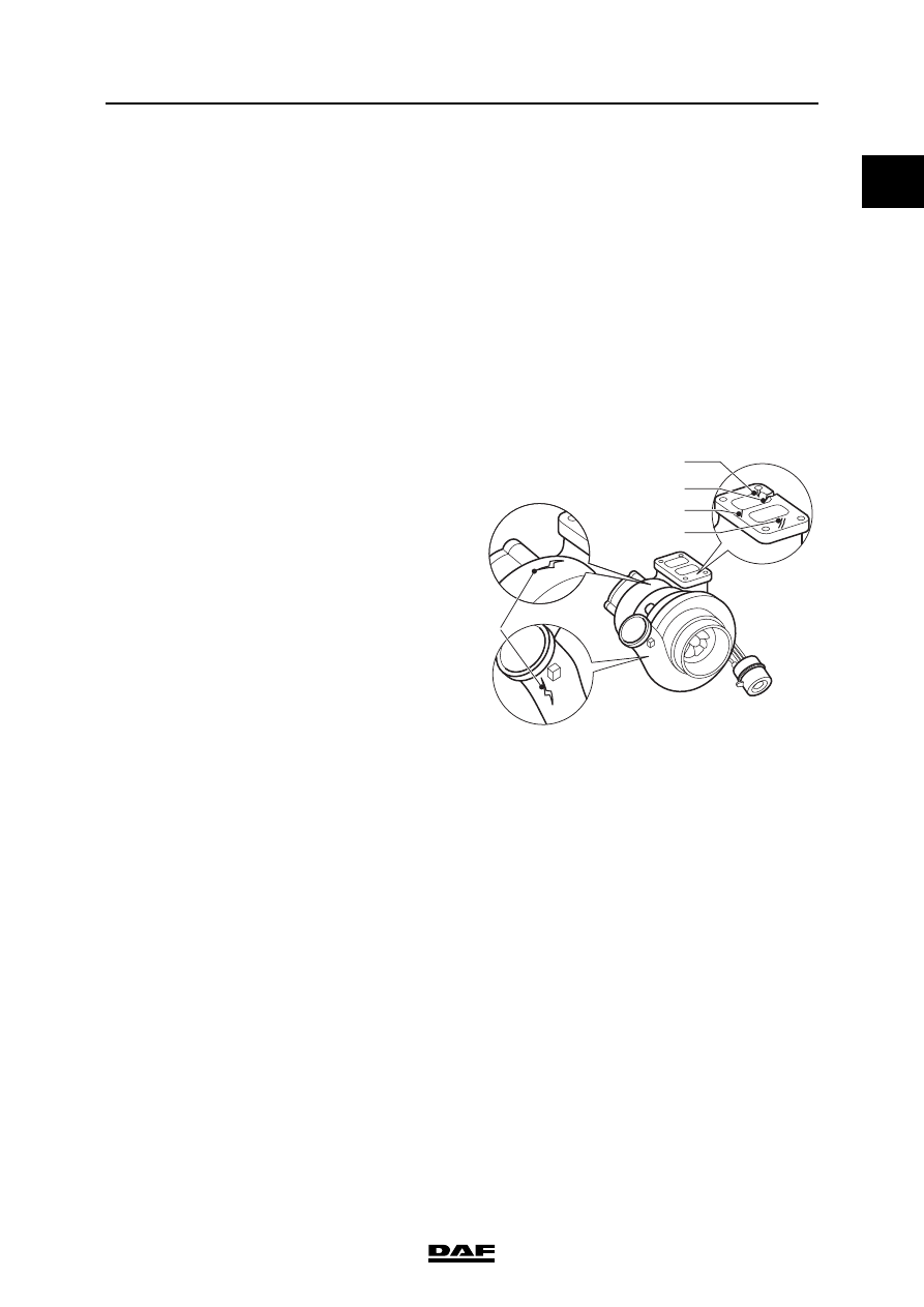
Turbocharger
Rejection standards for cracking
1.
Cracks in the connector flange must not
reach as far as the attachment holes.
2.
Cracks in the connector flange must not
reach from the channels as far as the
exterior.
3.
Cracks in the connector flange may not be
longer than 15 mm.
4.
Cracks in the connector flange must not be
less than 6 mm apart.
5.
There must be no cracks in the housing.
Exhaust gas back pressure
Inlet underpressure
Glow element
BE 99 C
Holset HX 27 W
BE 110 C
Holset HX 27 W
BE 123 C
Holset HX 27 W
Minimum actuating pressure of wastegate cap-
sule under which the control rod will move
2.0 bar
Axial bearing play of compressor shaft
0.057 - 0.103 mm
Radial bearing play of compressor shaft
0.39 - 0.67 mm
1
2
5
3
4
i400784
At full-load engine speed
100 mbar
Maximum back pressure during engine brake ap-
plication
4.3 bar
At full-load engine speed (clean air filter)
25 mbar
At full-load engine speed (clogged air filter)
62 mbar
Resistance value
180 - 220 m
TECHNICAL DATA
4-2
©
200416
BE Engine inlet/exhaust system
0
ΛΦ45/55 series
4
4.2 TIGHTENING TORQUES
The tightening torques specified in this section
are different from the standard tightening torques
cited in the overview of the standard tightening
torques. The other threaded connections not
specified must therefore be tightened to the
torque cited in the overview of standard
tightening torques.
When attachment bolts and nuts are replaced, it
is important that - unless stated otherwise - these
bolts and nuts are of exactly the same length and
property class as those removed.
Turbocharger
(1) Fasten with Copaslip
Intake manifold
Air cooler
Attachment nuts, exhaust manifold flange/turbo-
charger
43 Nm
Oil discharge pipe attachment bolts
23 Nm
Oil supply pipe union
28 Nm
Turbocharger V-clamp
10 Nm
Glow element attachment bolts
14 Nm
Hose clamps
7 Nm
©
200416
5-1
CE Engine inlet/exhaust system
TECHNICAL DATA
ΛΦ45/55 series
4
0
5. CE ENGINE INLET/EXHAUST SYSTEM
5.1 GENERAL
Turbocharger
Rejection standards for cracking
1.
Cracks in the connector flange must not
reach as far as the attachment holes.
2.
Cracks in the connector flange must not
reach from the channels as far as the
exterior.
3.
Cracks in the connector flange may not be
longer than 15 mm.
4.
Cracks in the connector flange must not be
less than 6 mm apart.
5.
There must be no cracks in the housing.
Exhaust gas back pressure
Inlet underpressure
Glow element
CE 136 C
Holset HY 35 W
CE 162 C
Holset HY 35 W
CE 184 C
Holset HX 35 W
Minimum actuating pressure of wastegate cap-
sule under which the control rod will move
2.0 bar
Axial bearing play of compressor shaft
0.038 - 0.093 mm
Radial bearing play of compressor shaft
0.329 - 0.501 mm
1
2
5
3
4
i400784
At full-load engine speed
100 mbar
Maximum back pressure during engine brake ap-
plication
4.3 bar
At full-load engine speed (clean air filter)
25 mbar
At full-load engine speed (clogged air filter)
62 mbar
Resistance value
180 - 220 m
TECHNICAL DATA
5-2
©
200416
CE Engine inlet/exhaust system
0
ΛΦ45/55 series
4
5.2 TIGHTENING TORQUES
The tightening torques specified in this section
are different from the standard tightening torques
cited in the overview of the standard tightening
torques. The other threaded connections not
specified must therefore be tightened to the
torque cited in the overview of standard
tightening torques.
When attachment bolts and nuts are replaced, it
is important that - unless stated otherwise - these
bolts and nuts are of exactly the same length and
property class as those removed.
Turbocharger
(1) Fasten with Copaslip
Glow element
Air cooler
Attachment nuts, exhaust manifold flange/turbo-
charger
43 Nm
Oil discharge pipe attachment bolts
23 Nm
Oil supply pipe union
28 Nm
Turbocharger V-clamp
10 Nm
Attachment bolts
14 Nm
Hose clamps
7 Nm
Нет комментариевНе стесняйтесь поделиться с нами вашим ценным мнением.
Текст