DAF LF45, LF55 Series. Manual — part 174
©
200505
4-31
Removing and installing
BE ENGINE
ΛΦ45/55 series
2
2
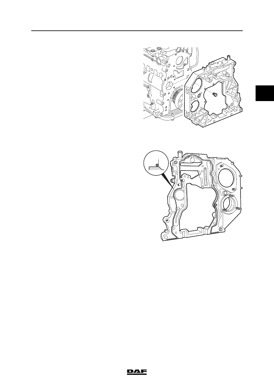
8.
Remove the attachment bolts from the timing
gear case and remove it.
Installing the timing gear case
1.
Apply a sealant to the sealing surface of the
cylinder block. See "Technical data". Apply
the sealant in accordance with the pattern
and at the indicated location. The bead has
to be 1.5 to 2.0 mm thick. Fit the timing gear
case with liquid sealant and tighten the
attachment bolts to the specified torque. See
"Technical data".
Note:
If too much sealant is used, or if the sealant
is applied in a wrong place, this may cause
obstruction of an oil channel or oil sump
ventilating duct. This could result in serious
damage.
2.
Fit the sump bolts and tighten them to the
specified torque. See "Technical data".
3.
Fit the camshaft gear.
4.
Fit the high-pressure pump.
5.
Fit the air compressor.
6.
Fit the steering pump.
7.
Fit the flywheel housing.
M201147
M201242
BE ENGINE
4-32
©
200505
Removing and installing
2
ΛΦ45/55 series
2
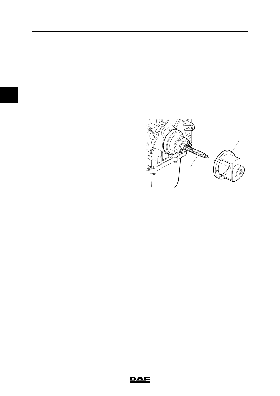
4.23 REMOVAL AND INSTALLATION, FRONT CRANKSHAFT SEAL
Removing the front crankshaft seal
1.
Remove the attachment bolts of the fan and
place the fan in the wind tunnel.
2.
Remove the poly-V-belt.
3.
Remove the attachment bolts from the
vibration damper and remove the damper
along with the crankshaft pulley.
4.
Fit the threaded spindle (2) of the special tool
(DAF no. 1453179) on the crankshaft flange.
5.
Screw the push/pull piece (1) onto the
spindle up to the engine panel.
Note:
Mark the drill at a length of 18 mm using a
piece of tape.
6.
Drill a hole through the base plate to the tape
marking and fit a screw in the seal to keep
the base plate in its place.
7.
Drill the other five holes and fit screws.
8.
Turn the threaded spindle (2) clockwise until
the seal has been removed.
M201069
2
1

©
200505
4-33
Removing and installing
BE ENGINE
ΛΦ45/55 series
2
2
Installing the front crankshaft seal
1.
Clean and inspect the seal chamber. Even
minimal damage may cause a leak.
2.
Fit the threaded spindle (2) of the special tool
(DAF no. 1453179) on the crankshaft flange.
3.
Put a new seal over the crankshaft.
4.
Screw the push/pull piece (1) onto the
threaded spindle (2) up to the seal.
5.
Turn the threaded spindle (2) anti-clockwise
until the push/pull piece (1) is level with the
top panel. The seal has been properly fitted
once it is level with the engine panel.
6.
Remove the special tool.
7.
Inspect the vibration damper.
8.
Fit the crankshaft pulley and the vibration
damper and tighten the attachment bolts to
the specified torque. See "Technical data".
9.
Fit the poly-V-belt.
10. Fit the fan.
M201069
2
1
BE ENGINE
4-34
©
200505
Removing and installing
2
ΛΦ45/55 series
2
Нет комментариевНе стесняйтесь поделиться с нами вашим ценным мнением.
Текст