DAF LF45, LF55 Series. Manual — part 395

17
1427090/03
EL001579
1
2
3
4
5
6
7
8
9
10
11
12
13
14
15
16
17
18
19
20
21
22
23
24
25
26
27
28
29
30
31
32
33
34
35
36
37
38
39
40
41
42
43
44
45
46
47
48
49
50
51
52
53
5189
4655
4655
2622
5055
5055
5055
1201
1201
RD
RD
RD
RD
GS
OE
RD
RD
ZT
ZT
BW
GL
GN
VT
GL
GS
GS
GS
GL
RD
5055
2622
2622
3
768
3
720
2
734
A11/701
8
751
B10/701
7
751
5
751
2
751
1
751
D942
1010
1000
1010
1000
E031
15A
1201
2
1
B043
6
751
4
751
4655
1
734
D900
A1/
743
C49/
745
E509
1
2
P
D787
1
2
E508
3
1
B377
M
1243
5
+
7
02
01
C893
2
1
B5
A5
B3
B4
A2
C892
A4
A1
B1
B2
200440
2-69
5
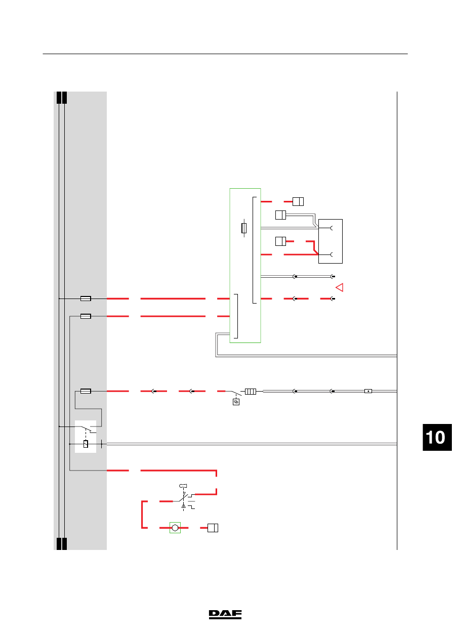
ELECTRICAL SYSTEM
Electrical system
series
45/55
LF

18.
SEA
T
H
EA
TING/ACCESSORIES
CONNECTION
SEA
T
H
EA
TING
When
the
vehicle
is
put
into
accessories
position,
relay
G
355
is
energised.
This
relay
supplies
power
to
the
driver
’s
side
seat
heating
system
(B032)
via
fuse
E
039
and
wire
1227.
If
the
seat
heating
switch
is
activated,
the
heating
element
will
start
w
arming
up.
When
the
m
aximum
temperature
is
reached,
a
thermal
switch
in
the
seat
heating
system
switches
of
ft
he
heating
element.
ACCESSORIES
CONNECTION
12
V
accessories
socket
A
01
1
is
connected
to
24
V/12
V
converter
D
958
through
a
w
hite
2-pin
connector
.12
V
is
applied
to
A
01
1
before
contact.
The
converter
is
supplied
w
ith
power
at
pin
3
after
contact
via
contact
switch
C
841
and
fuse
E026. The
“before
contact”
connection,
1000,
is
connected
via
fuse
E027
at
pin
2.
12
V
before
contact
is
applied
to
CB
connector
790
in
the
roof
console
through
connector
774
on
the
outside
of
the
central
box.
VARIANTS
Location 31
12
V
connector
,at
top
of
roof
console,
to
be
used
with
CB,
for
example.
200440
2-70
5
ELECTRICAL SYSTEM
Electrical system
series
45/55
LF
18
1427090/03
EL001580
1
2
3
4
5
6
7
8
9
10
11
12
13
14
15
16
17
18
19
20
21
22
23
24
25
26
27
28
29
30
31
32
33
34
35
36
37
38
39
40
41
42
43
44
45
46
47
48
49
50
51
52
53
1130
1105
1227
1227
1130
1105
1160
1160
1227
1153
1153
1108
1153
1153
1000
1000
1000
E349
1
2
B8/701
B9/701
B2/701
A2/701
A11/702
4
774
3
774
2
790
1
790
2
819
2
781
1
819
1
781
A011
1
2
!
B023
4
30
B023
7
30
B023
8
30
B032
2
1
D942
1010
1000
1010
1000
E039
20A
E026
20A
E027
10A
1226
1130
G355
3
1
24
5
M
7
65
49
3
24V
12V
12
D958
15A
C841
1/808
2/808
4/808
6/808
200440
2-71
5
ELECTRICAL SYSTEM
Electrical system
series
45/55
LF

19.
HORN/CIGAR
L
IGHTER/WORK
LAMP/AIR
DR
YER
HORN The
horn
(B401)
is
activated
before
contact
via
steering
column
switch
C
775
(1000).
T
he
horn
is
supplied
w
ith
power
via
w
ire
4979
and
fuse
E019.
CIGAR
L
IGHTER
If
the
ignition
switch
(C841)
is
in
the
accessories
position
(connection
between
contacts
1
and
6),
cigar
lighter
B030
is
supplied
w
ith
power
via
fuse
E
026
and
wire
1105.
By
depressing
the
cigar
lighter
,t
he
heating
element
is
warmed
up.
WORK
LAMP
W
ork
lamp
switch
C725
is
supplied
w
ith
voltage
from
power
supply
before
contact
and
via
fuse
E
052.
When
the
switch
is
operated
voltage
is
applied
to
the
work
lamp
(C071)
and
to
pin
C
9/745
of
the
V
IC
unit
in
order
to
ac
tiv
ate
the
“work
lamp”
indic
ator
on
the
DIP
via
I-CA
N
.
AIR
D
R
YER
When
the
ignition
switch
(C841)
is
on
(connection
between
contacts
1
and
4),
relay
G353
is
activated.
This
relay
supplies
power
to
the
air
dryer
heating
element
(B042)
via
fuse
E091
and
wire
1240.
When
the
m
aximum
temperature
is
reached,
a
thermal
switch
in
the
air
dryer
switches
of
f.
The
w
ater
separator
sensor
(F692)
is
supplied
with
power
via
the
same
wire.
VARIANTS
Location 20,24
Connector
780:
N
otf
itt
edo
nv
eh
ic
let
yp
eF
A
.
Wire
2155
only
fitted
in
application
connector
A
070
200440
2-72
5
ELECTRICAL SYSTEM
Electrical system
series
45/55
LF
Нет комментариевНе стесняйтесь поделиться с нами вашим ценным мнением.
Текст