DAF LF45, LF55 Series. Manual — part 109
1
LF45/55 series
General
CAB HEATING
2-1
2. GENERAL
2.1 SYSTEM DESCRIPTION OF HEATER, HEATER CONTROL
The heater is installed in the central console as
a complete unit.
The unit contains all control valves, control
handles and switches needed for ventilation and
heating.
There are two models:
-
heating/ventilation system
-
heating/ventilation system combined with
air conditioning.
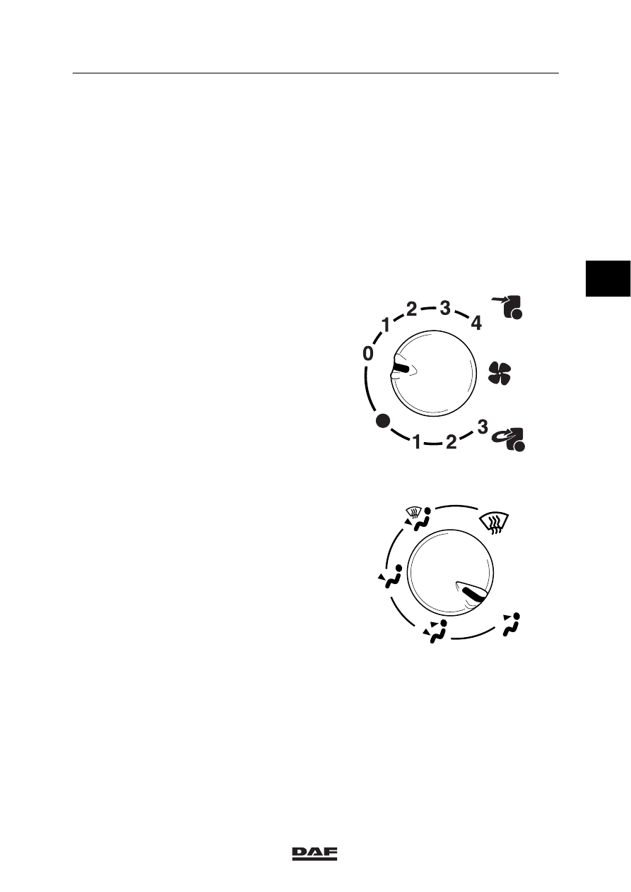
The control panel has three rotary knobs.
Knob 1
Five-position switch to control fan speed.
Three-position switch to control fan speed with
recirculation.
K1 01 197
Knob 2
Air outlets in the cab.
0
=
0-position
A
=
windscreen (defroster)
B
=
windscreen and leg area
C
=
leg area
D
=
leg area and dashboard
E
=
dashboard
K1 01 195
A
B
C
D
E
ǹ 0210
3
1
CAB HEATING
General
LF45/55 series
2-2
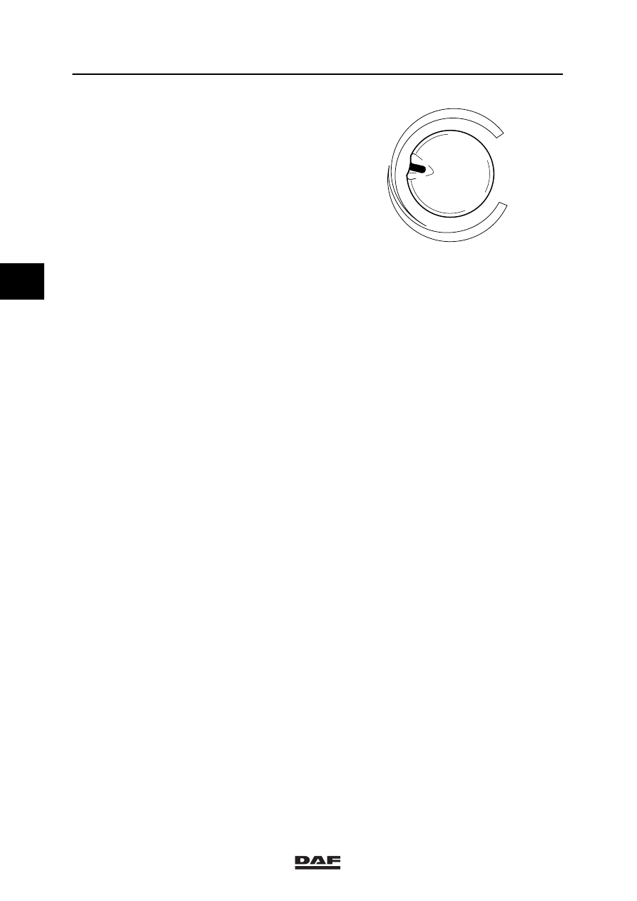
Knob 3
Temperature control: offers a continuously
variable supply of hot air from 0 to 100%.
K1 01 196
Air distribution
Optimal air distribution in the cab can be
achieved by means of knob 2 in combination
with the rotating and adjustable vents on the
central console and at the sides of the
dashboard.
3
ǹ 0210

1
LF45/55 series
Removal and installation
CAB HEATING
3-1
3. REMOVAL AND INSTALLATION
3.1 REMOVAL AND INSTALLATION, INTERIOR FILTER
Removing the interior filter
1.
Open the cab grille.
2.
Remove the attachment bolts (1) from the
grille on the underside of the filter casing.
3.
Open the grille (2) and remove the interior
filter.
Installing the interior filter
1.
Fit the interior filter, close the grille (2) and
fit the attachment bolts (1).
2.
Close the cab grille.
1
2
K1 01 147
3
ǹ 0210
1
CAB HEATING
Removal and installation
LF45/55 series
3-2
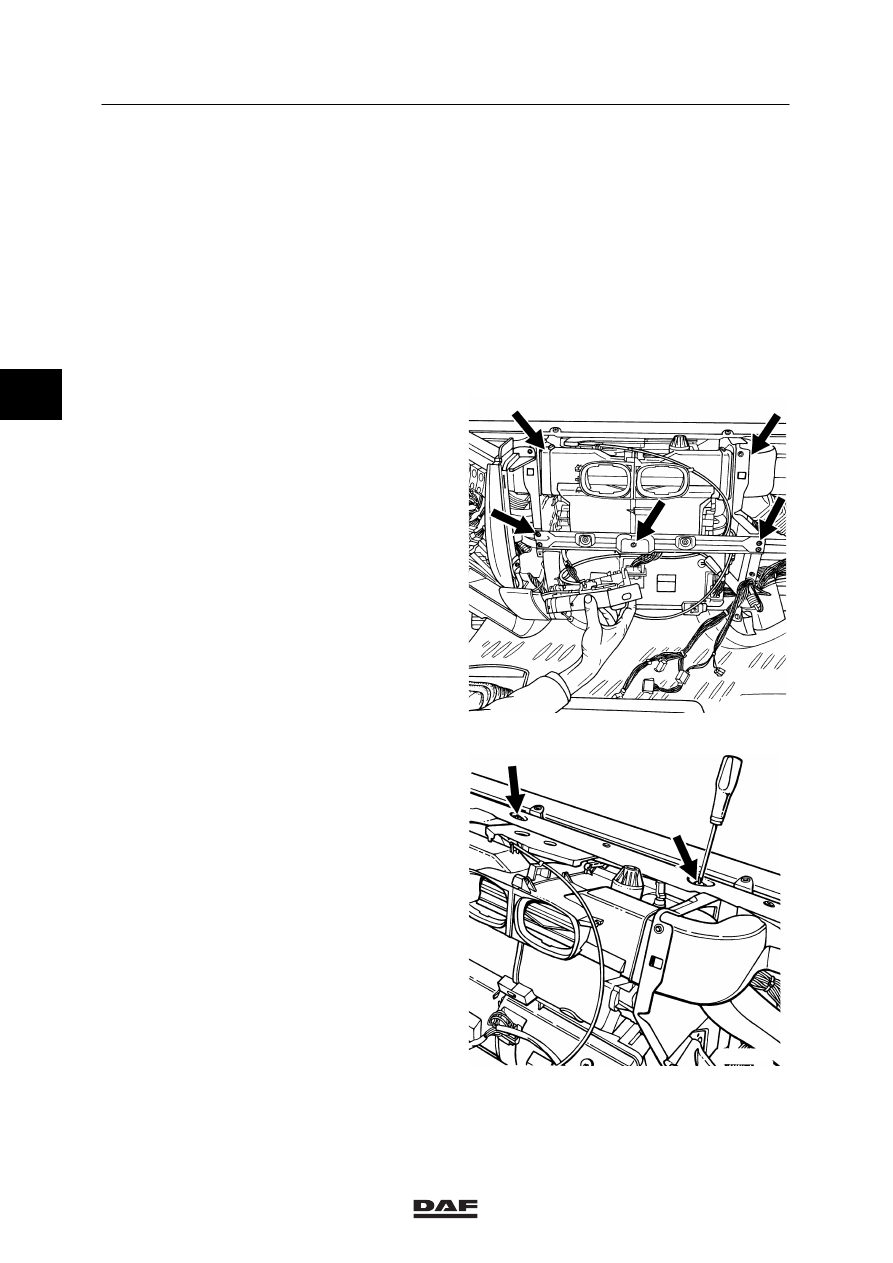
3.2 REMOVAL AND INSTALLATION, HEATER UNIT
Removing the heater unit
1.
Take the cover panel out of the window
frame.
2.
Remove all dashboard panels on the
underside.
3.
Remove the upper cover panel.
4.
Remove the dashboard panels on the
co-driver’s side. Remove the garnish
moulding around the instrument panel.
5.
Remove the attachment bolts from the
mounting plate at the front of the heater.
Remove the mounting plate and the upper
attachment bolts.
6.
Take the heater control out of the radio
panel and place it on the left-hand side of
the heater.
7.
Remove the heater unit connectors.
8.
Remove the heater unit air ducts.
K1 00 950
9.
Remove the upper attachment bolts from
the heater unit.
K1 00 951
3
ǹ 0210
Нет комментариевНе стесняйтесь поделиться с нами вашим ценным мнением.
Текст