DAF LF45, LF55 Series. Manual — part 106
1
LF45/55 series
Removal and installation
INTERNAL CAB COMPONENTS
4-31
4.11 REMOVAL AND INSTALLATION, INTERIOR LIGHTING
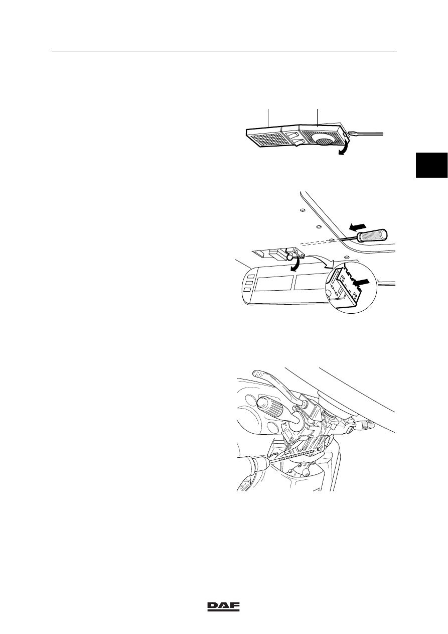
Removing the interior ceiling lighting
1.
Put a screwdriver between the glass cover
(1) and the holder (2).
2.
Remove the glass cover (1).
K1 01 169
1
2
3.
Bend the lock levers (B) inwards.
4.
Unplug the connectors and remove the
lamp holder.
Fitting the interior ceiling lighting
1.
Bend the lock levers (B) outwards.
2.
Hook up the connectors and fit the lamp
holder (2).
3.
Fit the glass cover (1).
K1 00 617
B
4.12 REMOVAL AND INSTALLATION, IGNITION LOCK
Removing the ignition lock
1.
Remove the covers around the steering
column under the steering wheel.
2.
Disconnect the connectors (behind the
dashboard).
3.
Drill off the head of the security bolt, use a
bit with the same diameter as the hole
where the head falls and remove the
ignition lock.
Installing the ignition lock
1.
Install the ignition lock.
2.
Tighten the security bolts with such a
tightening torque that the heads break off.
3.
Fit the covers around the steering column.
K1 01 134
2
ǹ 0210
1
INTERNAL CAB COMPONENTS
Removal and installation
LF45/55 series
4-32
4.13 REMOVAL AND INSTALLATION, COMPLETE DOOR LOCK MECHANISM
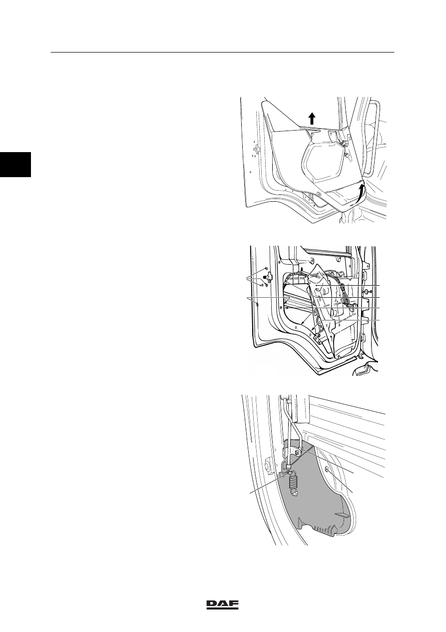
Removing the complete door lock
mechanism
1.
Close the window.
2.
Remove the door panel.
K1 01 408
3.
Gently remove the plastic screen (1) from
the door.
4.
Remove the attachment bolts (6) from the
closing mechanism.
5.
Remove the attachment bolts (5) from the
door lock mechanism.
6.
Remove the plug (4) from the central door
locking mechanism.
7.
Remove the clamping strips (3) holding in
place the main wiring harness (2) and the
wiring harness of the central door locking
mechanism.
8.
Lay the main wiring harness (2) aside
K1 01 439
1
2
3
4
5
6
9.
Remove the control rod by loosening the
control rod locking (1) through tilting and
unhooking the control rod from the locking.
10. Unhook the door lock mechanism from the
door and allow it to be lowered together with
the door locking
11. Remove the attachment bolts (3) from the
door lock mechanism.
1
2
3
K1 01 124
2
ǹ 0210
1
LF45/55 series
Removal and installation
INTERNAL CAB COMPONENTS
4-33
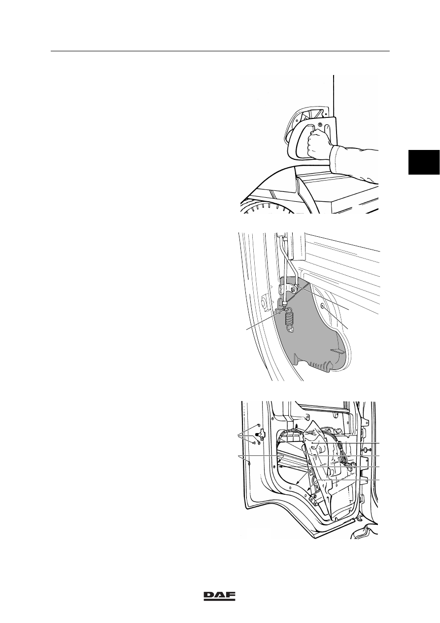
12. Remove the complete door lock mechanism
from the outside.
13. Remove the closing mechanism together
with the motor of the central door locking
from the inside of the door.
K1 01 171
Fitting the complete door lock mechanism
1.
Fit the closing mechanism in the door.
2.
Hook the control cable (3) in the door lock
mechanism.
3.
Position the door lock mechanism in the
door.
4.
Hook the control rod in the locking (1) of the
operating lever. Lock the control rod by
clicking the locking (1) in place over the
control rod.
1
2
3
K1 01 124
5.
Fit the attachment bolts (6) of the closing
mechanism.
6.
Fit the attachment bolts (5) of the door lock
mechanism.
7.
Fit the plug (4).
8.
Secure the main wiring harness (2), the
wiring harness of the central door locking
and the plug (4) to the threaded ends at the
inside of the door, using clamping strips.
9.
Fit the door screen (1).
10. Install the door panel.
K1 01 439
1
2
3
4
5
6
2
ǹ 0210
1
INTERNAL CAB COMPONENTS
Removal and installation
LF45/55 series
4-34
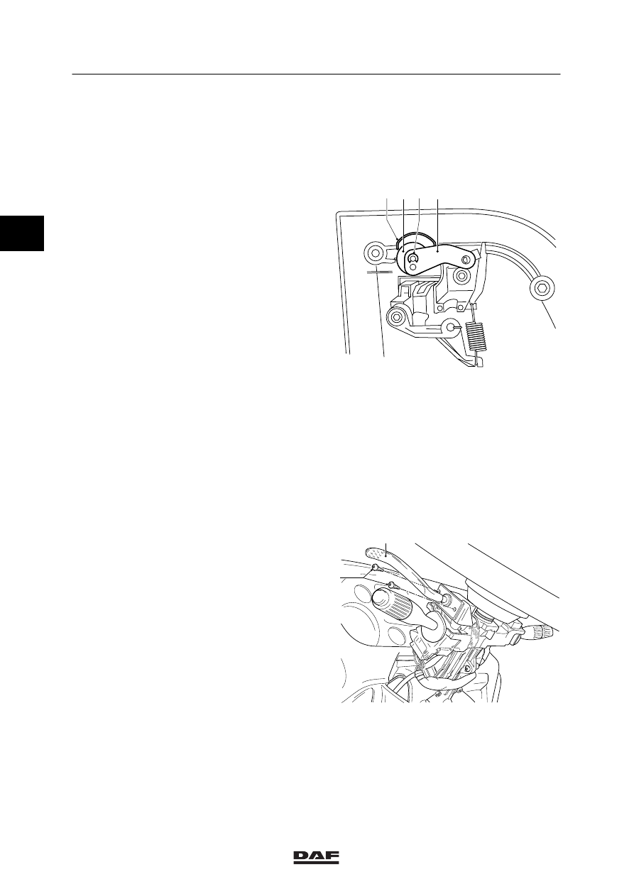
4.14 REMOVAL AND INSTALLATION, DOOR LOCK CYLINDER
Removing the door lock cylinder
1.
Remove the complete door lock
mechanism.
2.
Remove the circlip (3).
3.
Detach the operating lever (4).
4.
Loosen the locking spring (1) and remove
the door lock cylinder (2).
Fitting the door lock cylinder
1.
Fit the door lock cylinder (2). Fit the locking
spring (1).
2.
Fit the operating lever (4).
3.
Fit the locking ring (3).
4.
Fit the complete door lock mechanism.
1 2 3 4
K1 01 440
4.15 REMOVAL AND INSTALLATION, ENGINE BRAKE SWITCH
Removing the engine brake switch
1.
Remove the covers from the steering
column.
2.
Remove the engine brake switch connector
from the connector holder next to the
steering column.
3.
Remove the attachment bolts (1) from the
engine brake switch.
4.
Remove the engine brake switch (2).
Installing the engine brake switch
1.
Fit the engine brake switch (2).
2.
Secure the attachment bolts (1).
3.
Fit the connector.
4.
Fit the steering column covers.
1
2
K1 01 164
2
ǹ 0210
Нет комментариевНе стесняйтесь поделиться с нами вашим ценным мнением.
Текст