DAF LF45, LF55 Series. Manual — part 398
22
1427090/03
EL001586
107
108
109
110
111
112
113
114
115
116
117
118
119
120
121
122
123
124
125
126
127
128
129
130
131
132
133
134
135
136
137
138
139
140
141
142
143
144
145
146
147
148
149
1
50
151
152
153
154
155
156
157
158
159
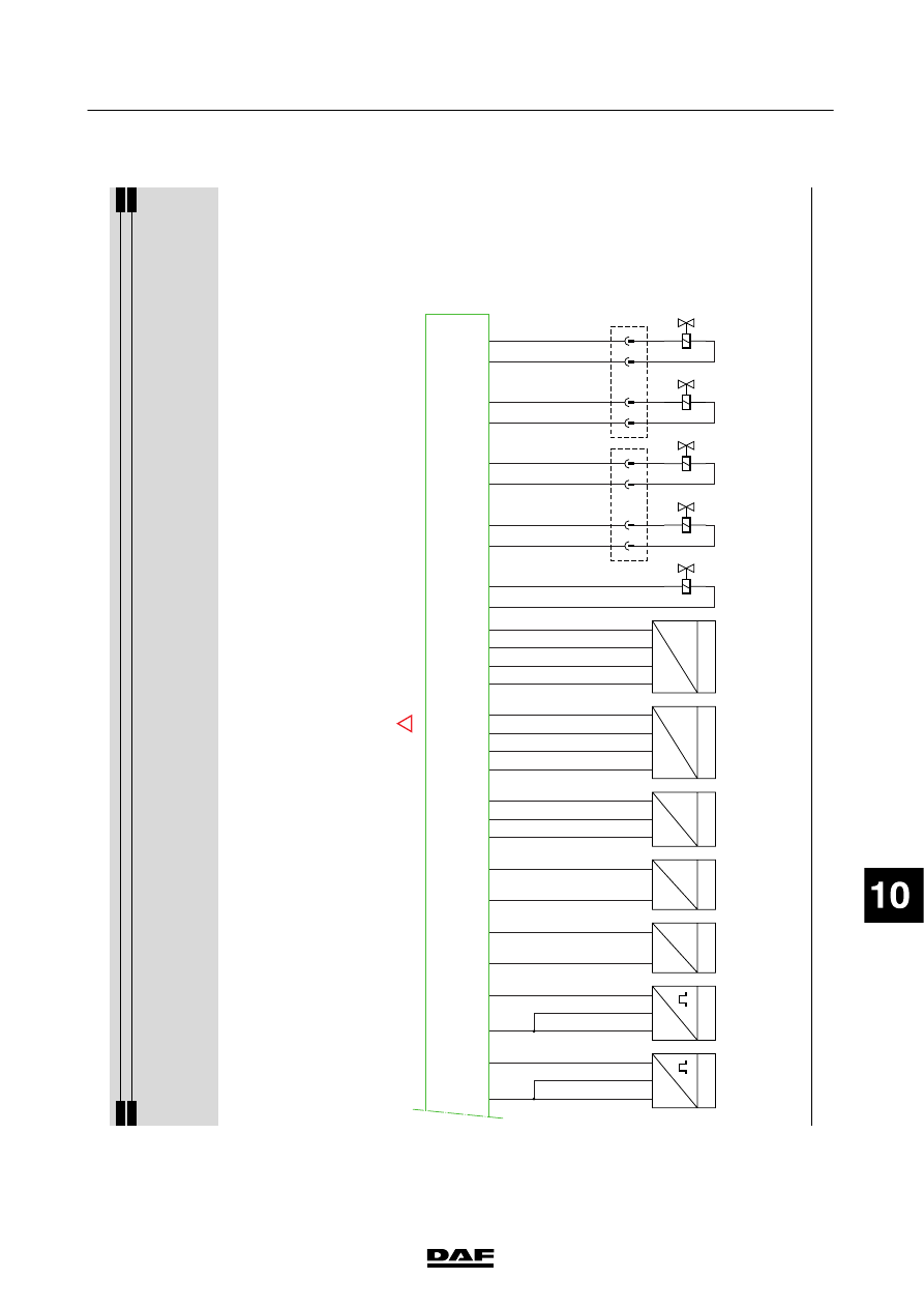
D942
1010
1000
1010
1000
T
R
F565
21
N
F552
32
1
WT
BW
RD
N
F558
32
1
WT/BN
BW
RD
P
U
F648
31
2
GN/GL
GN/OE
GN/BN
P&T
U&R
F647
32
1
4
VT/GL
VT/GN
VT/OE
VT/BN
P&T
U&R
F649
32
1
4
BN/GL
BN/GN
BN/OE
BN
GL/BW
GL/RD
T
R
F566
21
GL/OE
GL/BN
2
1
B334
2
1
B131
BN/WT
BN/VI
RD/GL
RD/GN
2
1
B132
RD/OE
RD/BN
2
1
B133
WT/GL
WT/GR
2
1
B134
WT/OE
WT/BN
A24/
827
A25/
827
D903
A30/
827
A23/
827
A34/
827
A17/
827
A12/
827
A27/
827
A20/
827
A9/
827
A33/
827
A35/
827
A19/
827
A10/
827
A28/
827
A29/
827
A21/
827
A7/
827
A5/
827
A36/
827
A18/
827
C9/
828
C13/
828
C10/
828
C15/
828
C11/
828
C16/
828
C4/
828
C12/
828
2
1
3
4
2
1
3
4
!
200440
2-81
5
ELECTRICAL SYSTEM
Electrical system
series
45/55
LF

22
1427090/03
EL001587
160
161
162
163
164
165
166
167
168
169
170
171
172
173
174
175
176
177
178
179
180
181
182
183
184
185
186
187
188
189
190
191
192
193
194
195
196
197
198
199
200
201
202
2
03
204
205
206
207
208
209
210
211
212
D942
1010
1000
1010
1000
T
R
F565
21
N
F552
32
1
WT
BW
RD
N
F558
32
1
WT
BW
RD
P
U
F648
31
2
GN/GL
GN/OE
GN/BN
P&T
U&R
F647
32
1
4
VT/GL
VT/GN
VT/OE
VT/BN
P&T
U&R
F649
32
1
4
BN/GL
BW/GN
BN/OE
BN
GL/BW
GL/RD
T
R
F566
21
GL/OE
GL/BN
2
1
B334
2
1
B131
BN/WT
BN/VI
RD/GL
RD/GN
2
1
B132
RD/WT
RD/BW
2
1
B133
WT/RD
WT/VI
2
1
B134
WT
WT/BW
2
1
B135
BW/GL
BW/GN
A24/
827
A25/
827
D903
A30/
827
A23/
827
A34/
827
A17/
827
A12/
827
A27/
827
A20/
827
A9/
827
A33/
827
A35/
827
A19/
827
A10/
827
A28/
827
A29/
827
A21/
827
A7/
827
A5/
827
A36/
827
A18/
827
C9/
828
C13/
828
C3/
828
C6/
828
C4/
828
C12/
828
C5/
828
C14/
828
C11/
828
C16/
828
C10/
828
C15/
828
2
1
B136
BW/OE
BW/BN
2
1
3
4
2
1
3
4
2
1
3
4
!
200440
2-82
5
ELECTRICAL SYSTEM
Electrical system
series
45/55
LF
200440
2-83
5
ELECTRICAL SYSTEM
Electrical system
series
45/55
LF

23.
CRUISE
CONTROL
The
right-hand
steering
column
switch
C
891
is
a
m
ulti-function
switch
for
w
indscreen
wiper/washer
functions
and
cruise
control/
engine
speed
control.
The
V
IC
sends
the
desired
commands
in
respect
of
vehicle/
engine
speed
to
the
E
CS-DC3
electronic
unit
via
the
CAN
network
(see
system
manual).
When
the
innermost
ring
of
switch
C891
is
rotated
(B5
with
B6),
power
is
supplied
to
pin
17/745.
The
“ON”
function
is
now
activated.
When
the
outermost
ring
of
switch
C891
is
rotated
downwards
(B2
w
ith
B
1),
power
is
supplied
to
pin
C18/745.
This
activates
the
“SET+”
function.
When
the
outermost
ring
of
switch
C891
is
rotated
upwards
(B2
w
ith
B
7),
power
is
supplied
to
pin
C19/745.
This
activates
the
“RES
--”
function.
Operating
the
RES
button
at
the
end
of
the
switch
has
the
same
ef
fect
as
turning
the
“RES
--”
rotary
switch.
200440
2-84
5
ELECTRICAL SYSTEM
Electrical system
series
45/55
LF
Нет комментариевНе стесняйтесь поделиться с нами вашим ценным мнением.
Текст