DAF LF45, LF55 Series. Manual — part 410
37
1427090/03
EL001610
54
55
56
57
58
59
60
61
62
63
64
65
66
67
68
69
70
71
72
73
74
75
76
77
78
79
80
81
82
83
84
85
86
87
88
89
90
91
92
93
94
95
96
97
98
99
100
101
102
103
104
105
106
2647
2647
2647
2600
2003
2003
3412
3652
2003
3412
3412
3412
2003
3479
2600
2647
2647
2647
2600
1107
2600
2600
2600
1107
1107
3700K
3701K
3700D
3701D
3412
1357
1357
1264
3482
1264
1264
3482
1229
1229
E515
1
2
E514
1
2
A13/703
A11/703
7/709
A12/703
D23/
746
B16/
744
C36/
745
C14/
745
C15/
745
D22/
746
D1/
746
D900
C765
6
7
F009
2
1
B11
713
G520
B5/
797
B11/
797
B10/
797
A8/
796
B20/
797
A9/
796
B21/
797
D911
B6/702
B1/702
2
740
1
740
D931
1/
807
2/
807
3/
807
4/
807
5/
807
D942
1010
1000
1010
1000
E028
15A
2600
E053
10A
E143
10A
D715
2
1
!
D758
798
798
200440
2-129
5
ELECTRICAL SYSTEM
Electrical system
series
45/55
LF
38.
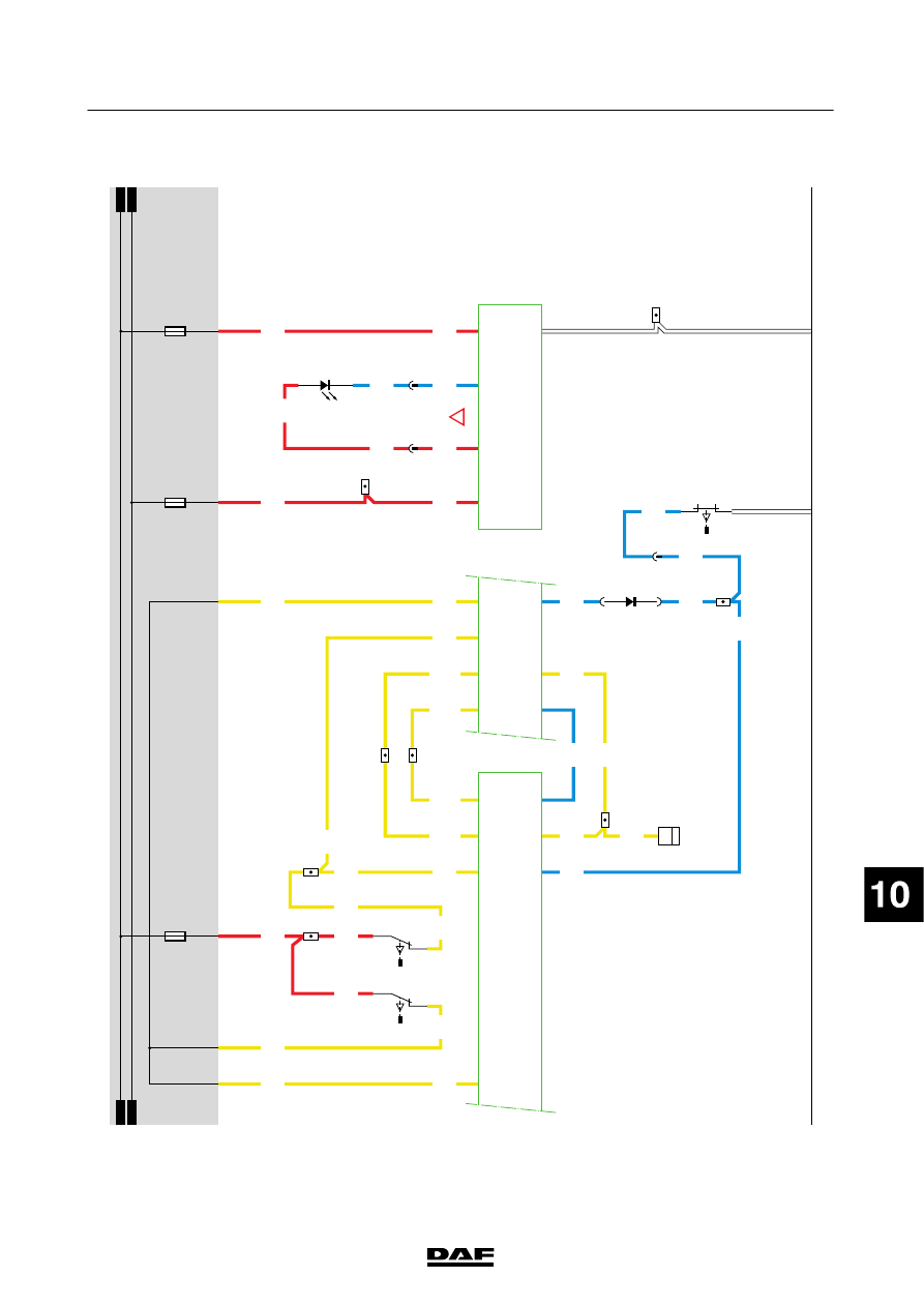
SOCKETS,
FA/FT
12
V
P
LUG
(A01
1)
Pin
1
is
connected
to
the
24/12
V
converter
(12
V
before
contact)
through
wire
1153.
Pin
2
is
connected
to
the
earth
connection
of
the
converter
.
DIAGNOSTIC
SOCKET
(A021)
The
diagnostic
socket
is
located
to
the
left
of
the
driver
’s
seat
on
the
floor
plate.
This
is
the
socket
for
the
D
AV
IE
connection.
Power
before
contact
is
supplied
to
pin
1
through
fuse
E053.
Pin
2
is
connected
to
earth.
T
he
remaining
pins
are
for
communicat
ion
wit
h
th
e
various
syst
ems
and
are
connected
to
those
systems.
Pin
no.
W
ire
no.
Colour
Description
1
1229
red
P
ower
supply
before
contact
2
9107
white
E
arth
3
3425
blue
ABS-D/ABS/ASR-E
4-
5-
6-
7
4732
black
E
CAS-3/ECAS-2
8
3646
blue
CDS,
A
LS-S,
airbag/seat
belt
tensioner
,R
AS-EC
9
4047
black
V
IC
10
-
11
-
12
4733
black
D
IP-4
13
-
14
3037
blue
Cab
heater
15
3700
yellow
C
AN-network
(ECS-DC3,
M
TCO)
16
3701
blue
CAN-network
(ECS-DC3,
M
TCO)
200440
2-130
5
ELECTRICAL SYSTEM
Electrical system
series
45/55
LF
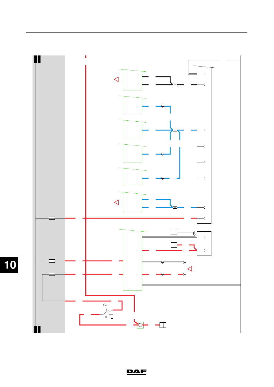
DRA
WN
VEHICLE
SOCKET
(A000)
(7
-p
in)
Pin
1
connected
to
earth.
When
a
connection
is
made
between
contacts
2
and
1
(marker
light/parking
light
position)
by
switching
on
the
lighting
switch
(C622),
relay
G000
is
energised.
Relay
G
000
supplies
power
to
wire
2101
via
w
ire
1000.
V
ia
fuses
E284
and
E283,
power
is
supplied
to
connector
A
000
at
pin
2
(via
w
ire
2170)
and
pin
6
(via
w
ire
2169)
respectively
.
Pin
2
switches
the
left-hand
rear
light.
Pin
3
is
connected
via
wire
2008
to
connection
point
E7/747
of
the
VIC
(D900)
(direction,
left).
Pin
4
is
connected
via
wire
4601
and
fuse
E013
to
relay
G
036
(brake
light
relay).
Pin
5
is
connected
via
wire
2008
to
pin
E4/747
of
the
V
IC
(D900)
(direction,
right).
Pin
6
switches
the
right-hand
rear
light.
Pin
7
-
SUPERSTRUCTURE
APPLICA
T
ION
CONNECT
OR
(A070)
Pin
1
connected
to
power
before
contact
via
wire
11
10
and
fuse
E052.
Pin
2
on
vehicle
type
FA,
connected
to
the
V
IC
and
the
w
ork
lamp
switc
h
(C725)
through
wire
2155,
fuse
E283
and
wire
2101.
On
vehicle
type
FT
,p
in
2
is
connected
to
the
right-hand
rear
light
through
wire
2169
.
Pin
3
connected
to
connection
point
5
of
G036
(stop
light
relay)
via
w
ire
4601
and
fuse
E013.
Pin
4
connected
via
wire
4591
to
connection
point
2
of
E
501
(reversing
lamp
switch).
Pin
5
connected
to
connection
point
A6/796
of
D91
1
(electronic
unit,
alarm
syst
em
A
LS
-S
)
via
w
ire
1264.
Pin
6
connected
to
connection
point
B6/797
of
D91
1
(electronic
unit,
alarm
syst
em
A
LS
-S
)
via
w
ire
3659.
Pin
7
connected
to
connection
point
B4/797
of
D91
1
(electronic
unit,
alarm
syst
em
A
LS
-S
)
via
w
ire
3660.
Pin
8
connected
directly
to
earth
point
G520.
REAR
FOG
L
AMP/REVERSING
LIGHT
SOCKET
(A001)
Pin
1
connected
to
earth.
Pin
2
-
Pin
3
connected
via
wire
4591
to
pin
2
of
E501
(reversing
lamp
switch).
Pin
4
connected
via
wire
11
10
to
power
before
contact
(1000)
via
fuse
E052.
Pin
5
-
Pin
6
connected
via
wire
1356
to
power
after
contact
(1010)
via
fuse
E282.
Pin
7
connected
via
wire
2152
to
relay
G005
(rear
fog
lamp
relay).
DRA
WN
VEHICLE
ABS/EBS
SOCKET
(A004) Pin
1
of
the
drawn
vehic
le
ABS/EBS
socket
(A004)
is
connected
directly
to
power
before
contact
via
fuse
E
043
and
wire
11
19.
Pin
2
connected
directly
to
power
after
contact
via
fuse
E282
and
wire
1356.
Pin
3
connected
to
earth.
Pin
4
connected
to
earth.
Pin
5
connected
to
pin
C32/745
of
the
VIC
(D900)
via
w
ire
3428.
Pin
6
-
Pin
7
-
VARIANTS
Location 26
Elec
tronic
unit,
ABS/ASR,
E
version
(D961):
Or
electronic
unit
for
ABS/ASR,
D
version
(D941)
49
Electronic
unit,
ECAS-3
(D851):
Or
electronic
unit
E
CAS-2
(D802)
79,81,91, 117,126,135
Connector
762:
N
otf
itt
edo
nv
eh
ic
let
yp
eF
T
86,88,122, 129,144, 148,150
Connector
763:
N
otf
itt
edo
nv
eh
ic
let
yp
eF
T
200440
2-131
5
ELECTRICAL SYSTEM
Electrical system
series
45/55
LF
38
1427090/03
EL001611
1
2
3
4
5
6
7
8
9
10
11
12
13
14
15
16
17
18
19
20
21
22
23
24
25
26
27
28
29
30
31
32
33
34
35
36
37
38
39
40
41
42
43
44
45
46
47
48
49
50
51
52
53
1000
1000
1105
1229
1105
1160
1160
1130
1130
1153
9107
3425
3425
1153
1000
1000
1000
3425
3646
3646
3646
3646
3646
3646
3646
3646
3646
1229
1153
1153
1153
4732
4732
4732
E349
1
2
B8/701
B9/701
A2/701
17
65
4
32
D958
A011
1
2
B023
4
30
B023
8
30
5/712
A021
1
2
7
4
3
5
6
8
A10/
820
A11/
820
D961
10/
737
D905
B15/
797
D911
15/
837
D940
9/
802
D926
4
774
3
735
7
720
3
801
3
774
2
790
1
790
!
D942
1010
1000
1010
1000
E026
20A
E027
10A
E053
10A
1130
C841
1/808
2/808
4/808
6/808
3/
748
4/
748
D851
!
!
200440
2-132
5
ELECTRICAL SYSTEM
Electrical system
series
45/55
LF
Нет комментариевНе стесняйтесь поделиться с нами вашим ценным мнением.
Текст