DAF LF45, LF55 Series. Manual — part 177
©
200505
3-1
Description of components
BE ENGINE COOLING SYSTEM
ΛΦ45/55 series
2
3
3. DESCRIPTION OF COMPONENTS
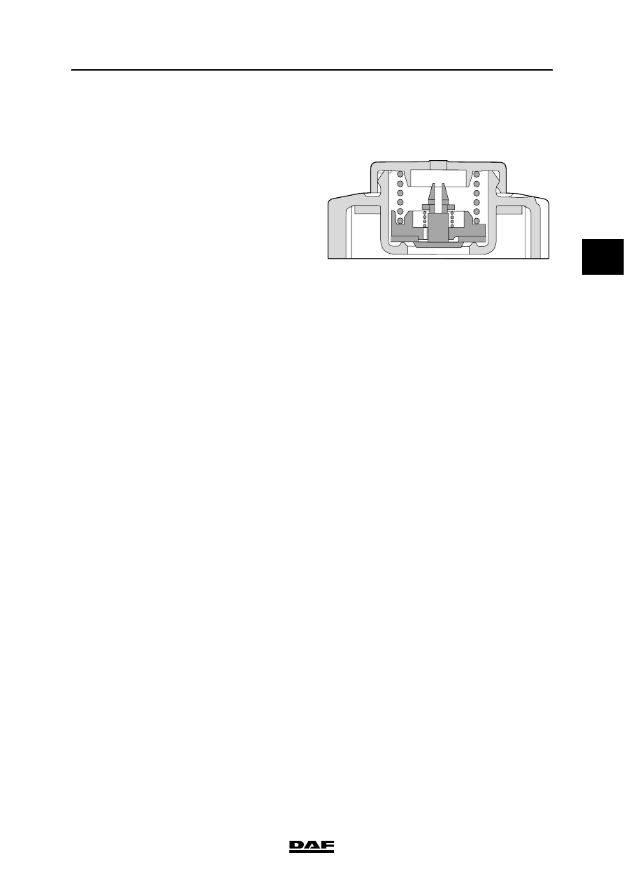
3.1 PRESSURE CAP
The pressure cap is fitted on the header tank by
means of a threaded connection.
To fill the cooling system, there is a filler cap at
the front of the header tank.
The pressure cap has two valves: a pressure
relief valve and a vacuum relief valve.
Normally, both valves are closed.
Overpressure
As a result of the rising coolant temperature, the
pressure (P1) in the cooling system will increase.
If the pressure in the cooling system becomes too
high (0.7 bar), the pressure relief valve (1) will
open against the pressure of the spring.
Negative pressure
If the coolant temperature drops, the pressure
(P1) in the cooling system will decrease. If the
pressure (P1) in the cooling system drops to
approximately 0.1 bar below the ambient air
pressure (P2), the underpressure valve will be
opened.
M201151
P2
P1
BE ENGINE COOLING SYSTEM
3-2
©
200505
Description of components
3
ΛΦ45/55 series
2
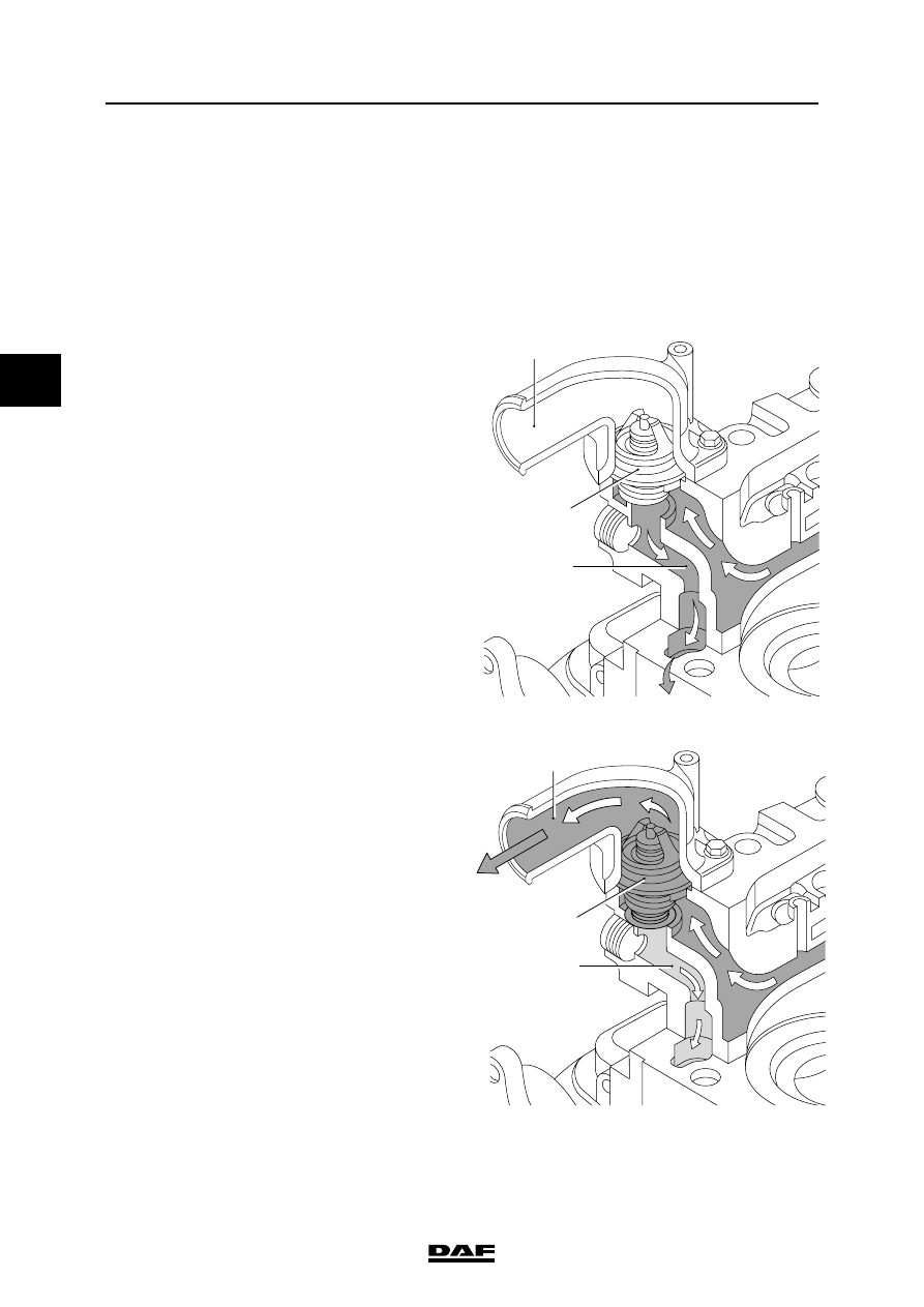
3.2 THERMOSTAT
Operation, thermostat
Coming from the cylinder head, the coolant
passes through the thermostat. Depending on the
coolant temperature and the corresponding
position of the thermostat, there are three
possibilities:
Thermostat closed
The coolant has not yet reached the opening
temperature of the thermostat (1).
The supply channel (B) to the radiator is
completely closed.
The coolant flows directly to the water pump
through a bypass (A) and the water pump returns
the coolant to the cylinder block.
Thermostat starts opening
The coolant has reached the opening
temperature of the thermostat (1).
The supply channel (B) to the radiator is opened
and the bypass (A) is partially closed.
Now coolant will flow both through the supply
channel (B) to the radiator and directly to the
water pump through the bypass channel (A).
1
A
B
M201126
M201127
1
A
B
©
200505
3-3
Description of components
BE ENGINE COOLING SYSTEM
ΛΦ45/55 series
2
3
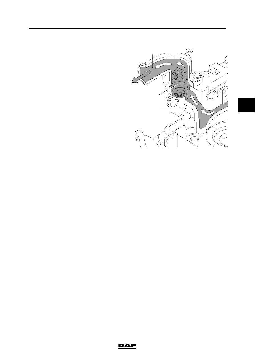
Thermostat fully opened
The temperature of the coolant has further
increased. The supply channel (B) to the radiator
is fully opened and the bypass (A) is fully closed.
The entire coolant circulation now flows via the
supply channel (B) to the radiator where it is
cooled before flowing back to the water pump.
In the event of excessive coolant temperatures,
removing the thermostat as an emergency
solution is not permitted.
If the thermostat is removed from the engine,
uncooled coolant will flow to the water pump
through the bypass (A). As a result, the coolant
temperature will continue to rise.
M201128
1
A
B
BE ENGINE COOLING SYSTEM
3-4
©
200505
Description of components
3
ΛΦ45/55 series
2
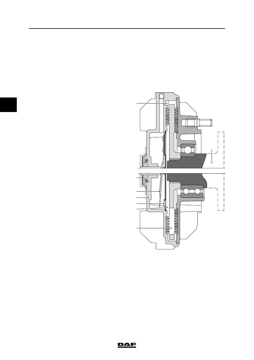
3.3 VISCOUS FAN CLUTCH
The fan is connected to the engine by means of a
viscous fan clutch. If, under certain
circumstances, the heat is not sufficiently
dissipated by the air flow passing through the
radiator, the fan will have to draw in extra cooling
air through the radiator. In a viscous fan clutch,
the drive torque is transmitted by a silicone fluid.
The fan clutch is divided into two chambers. In the
working area (1) is the rotor (2), which is
connected to the drive flange (7). The supply
chamber (3) rotates freely round the drive flange
(7) and is connected to the fan. There is silicone
fluid in the supply chamber (3). The opening (4) in
the supply chamber (3) is closed by a valve (5).
The valve (5) is operated by a bimetallic strip (6).
If the opening (4) in the supply chamber (3) is
closed by the valve (5), no silicone fluid can enter
the working area (1). The silicone fluid still
present in the working area (1) will flow back to
the supply chamber (3) through the bores (8). As
only very little fluid will be left in the working area
(1), there will be a great difference in rotating
speed (slip) between the drive flange (7) and the
supply chamber (3) with the fan.
When the air temperature increases, the
bimetallic strip (6) will bend and the valve (5) will
partially release the opening (4) in the supply
chamber (3). Through this opening, a limited
amount of silicone fluid can enter the working
area (1) and flow past the rotor (2). This will cause
friction, so that the difference in rotating speed
(slip) between the drive flange (7) and the supply
chamber (3) with the fan will decrease.
M201039
6
8
7
5
2
3
4
1
Нет комментариевНе стесняйтесь поделиться с нами вашим ценным мнением.
Текст