DAF LF45, LF55 Series. Manual — part 434
©
200436
1-1
Brake system and components
TECHNICAL DATA
ΛΦ45/55 series
6
0
1. BRAKE SYSTEM AND COMPONENTS
1.1 GENERAL
Coding of components
All components have been provided with number
codes.
Structure of the code
First digit
Often used:
Little used:
Where one connection performs several
functions, additional 1
st
digits will be allocated.
These are separated by a hyphen.
Second digit
If there are several connections with the same
function, a 2
nd
digit will be added immediately
after the 1
st
one.
Application example: empty/load relay valve
Meaning:
COMPRESSOR
Knorr model
1
Energy supply (pressure)
2
Energy discharge (outgoing command)
3
Bleed
4
Control connection (incoming command)
0
Suction connection
5
Free
6
Free
7
Anti-freeze connection
8
Lubricating oil connection
9
Coolant connection
1
Air compressor energy supply
2
Energy discharge (command) to the next
component
41
Control connection (incoming)
42
Second control connection (incoming)
Type: LK3839
Version:
1-cylinder, liquid-cooled
TECHNICAL DATA
1-2
©
200436
Brake system and components
0
ΛΦ45/55 series
6
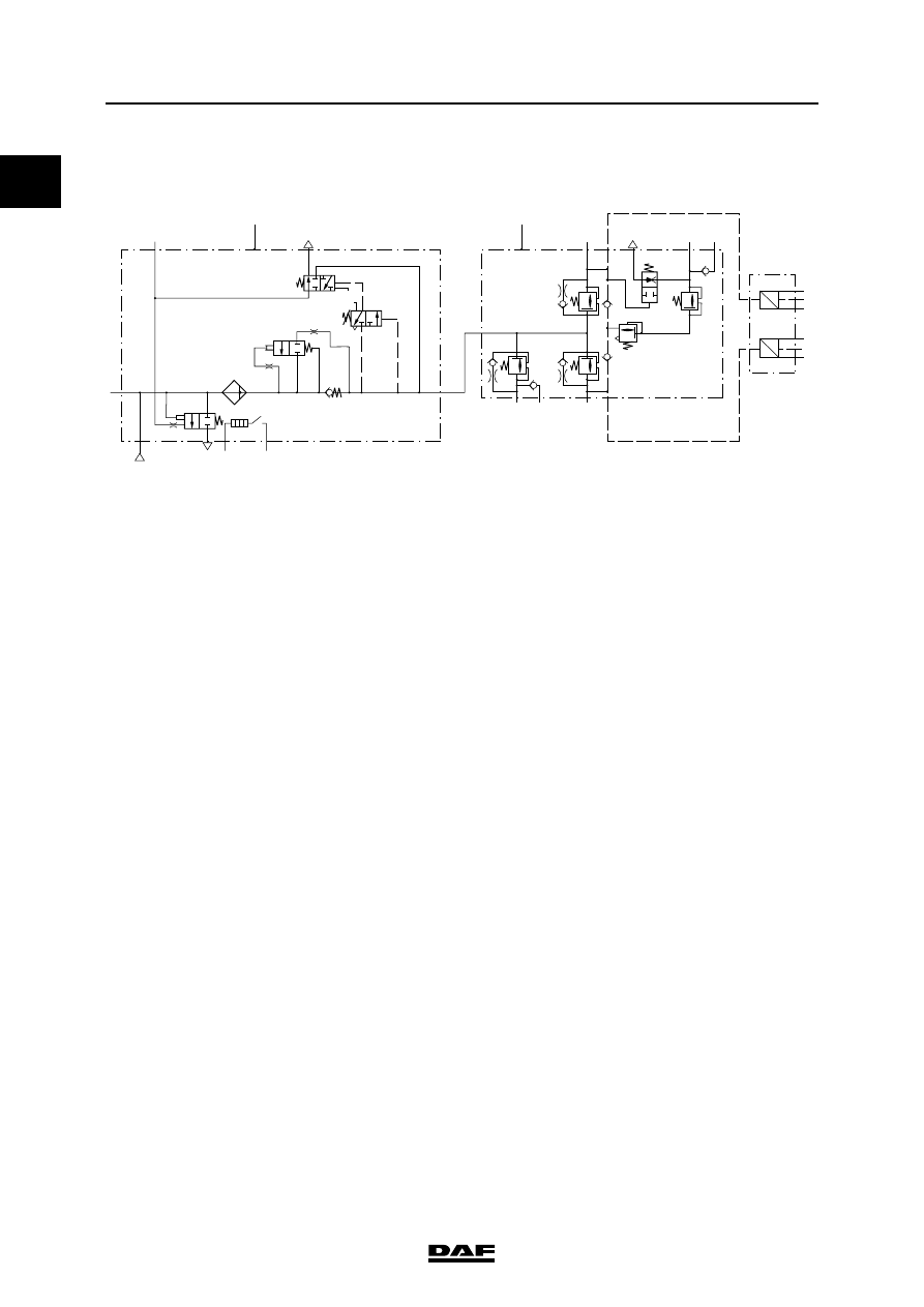
AIR SUPPLY UNIT
Front axle, leaf-sprung
24
21
1
F
D
N
J
K
L
M
H
P
3
A
E
C
G
1
12
26
22
21
23
3
23 25
P
U
6.2
6.3
6.4
6.1
6.2
P
U
6.5
6.6
6.7
B
R600702
0
A
Air dryer/pressure regulator (unit)
B
4-circuit protection valve (unit)
C
Filter/drying grid
D
Pressure regulator
E
Blow-off valve
F
Pneumatic time switch for regeneration
G
Heating element
H
Pressure relief valve with bypass, circuit 1
J
Pressure relief valve with bypass, circuit 2
K
Pressure limiting valve, circuit 3
L
Pressure relief valve, circuit 3
M
Flowback valve, circuit 3
N
Pressure relief valve with bypass, circuit 4
P
Pressure sensors
Cut-out pressure of pressure regulator
10.0
≥ 0.2 bar
Cut-in pressure of pressure regulator
1.2
≥ 0.2 bar under cut-out pressure
Supply pressure in circuit 1, connection 21
max. 10 bar
Supply pressure in circuit 2, connection 22
max. 10 bar
Supply pressure in circuit 3, connection 23
8.5 - 0.4 bar
Supply pressure in circuit 3, connection 25
8.5 - 0.6 bar
Supply pressure in circuit 4, connection 24
max. 10 bar
Supply pressure in circuit 4, connection 26
max. 10 bar
Opening pressure of circuits 1, 2 and 4
8.5 bar
Opening pressure of circuit 3
7.0 bar
Closing pressure of circuits 1, 2 and 4
7 bar
Closing pressure of circuit 3
5.5 bar
Cut-in temperature of heating element
7
C
Cut-out temperature of heating element
29
C
Circuit 1 activation pressure for flowback function
of circuit 3
< 4.5 bar
©
200436
1-3
Brake system and components
TECHNICAL DATA
ΛΦ45/55 series
6
0
Pressure sensor reading, circuits 1 and 2
(connections 6.2 - 6.7 in the diagram above)
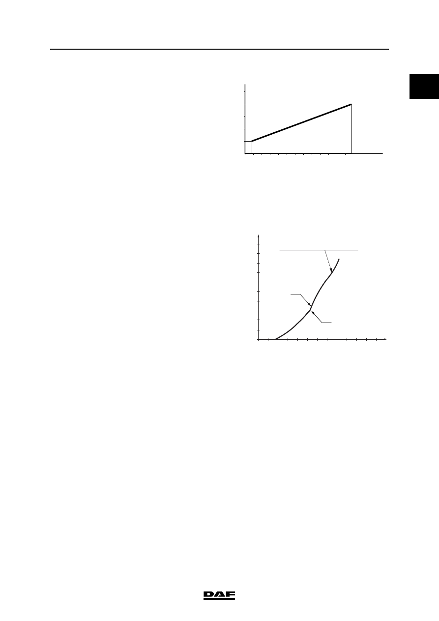
FOOT BRAKE VALVE
Pressure reduction in circuits 1 and 2 from 10 to
8 bar
1V
0V
2V
3V
4V
5V
12
0
2
4
6
8
10
P
21.22
(bar)
U
a
(V)
R600701
4
5
6
7
8
9
10
bar
P21
P22
3
2
1
1 2 3 4 5 6 7 8 9 10 11 12
C
(cm)
0
P21-P22 = 0,3
– 0,15
bar
21
22
R600594
Pressure difference between circuits 1 and 2 (be-
tween 0 and 3 bar)
0.3
≥ 0.15 bar
Connection 11
circuit 1 supply
Connection 12
circuit 2 supply
Connection 21
circuit 1 braking pressure
Connection 22
circuit 2 braking pressure
TECHNICAL DATA
1-4
©
200436
Brake system and components
0
ΛΦ45/55 series
6
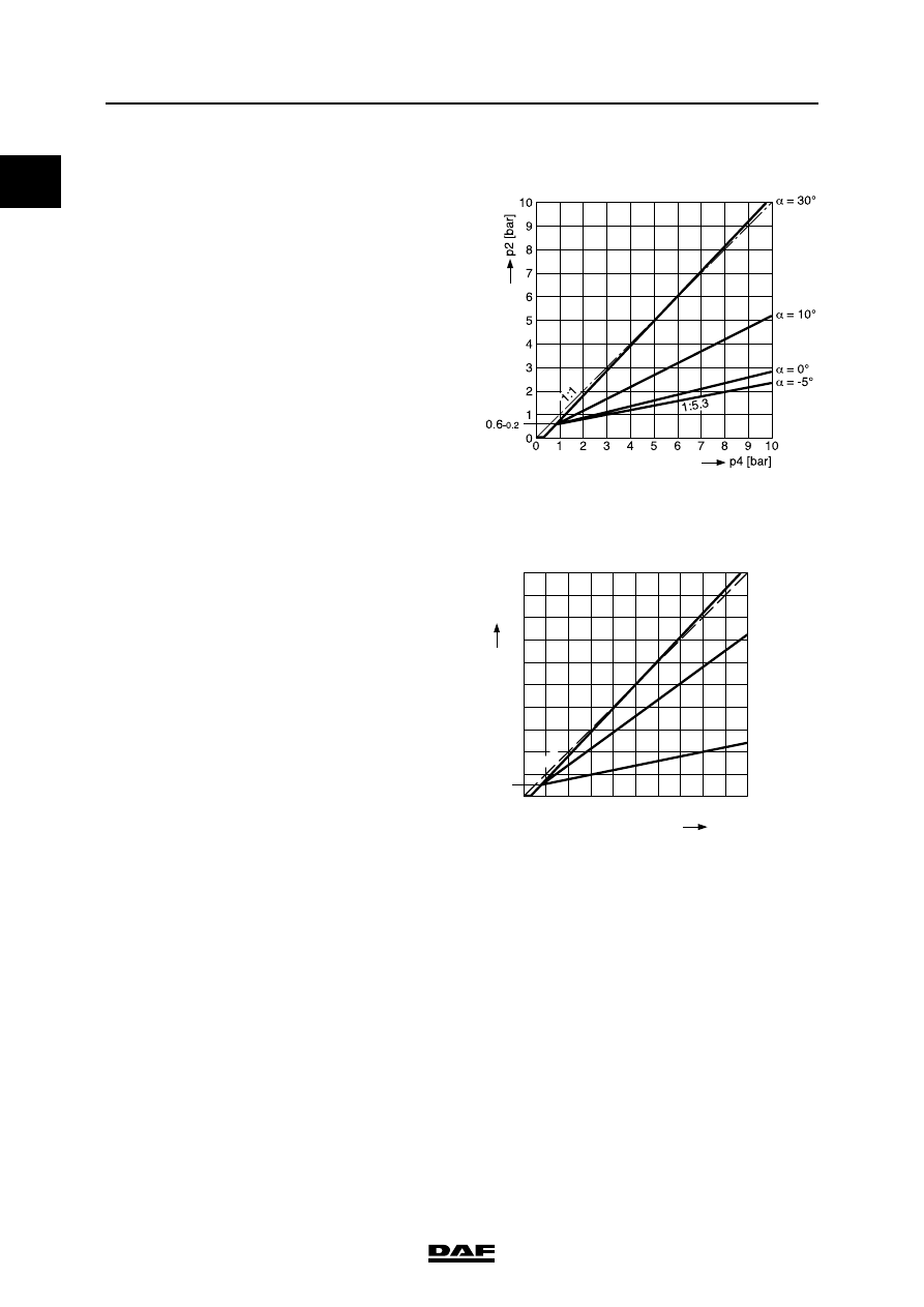
LOAD-DEPENDENT CONTROL VALVE,
LEAF SPRING
Characteristic
LOAD-DEPENDENT CONTROL VALVE,
AIR SUSPENSION
Characteristic
LOW-PRESSURE SWITCH
R600704
1
0
0.6
–0.2
1
2
3
4
5
6
7
8
9
10
2
3
4
5
6
7
8
9
10
R600705
p41
p42
= 4.65 bar
p41
p42
= 3 bar
p41
p42
= 0.3 bar
p4 [bar]
p2 [bar]
1:1
Cut-out pressure:
5.2
≥ 0.2 bar
Нет комментариевНе стесняйтесь поделиться с нами вашим ценным мнением.
Текст