DAF LF45, LF55 Series. Manual — part 559
7
LF45/55 series
Removal and installation
STEERED TRAILING SWIVEL AXLE
3-11
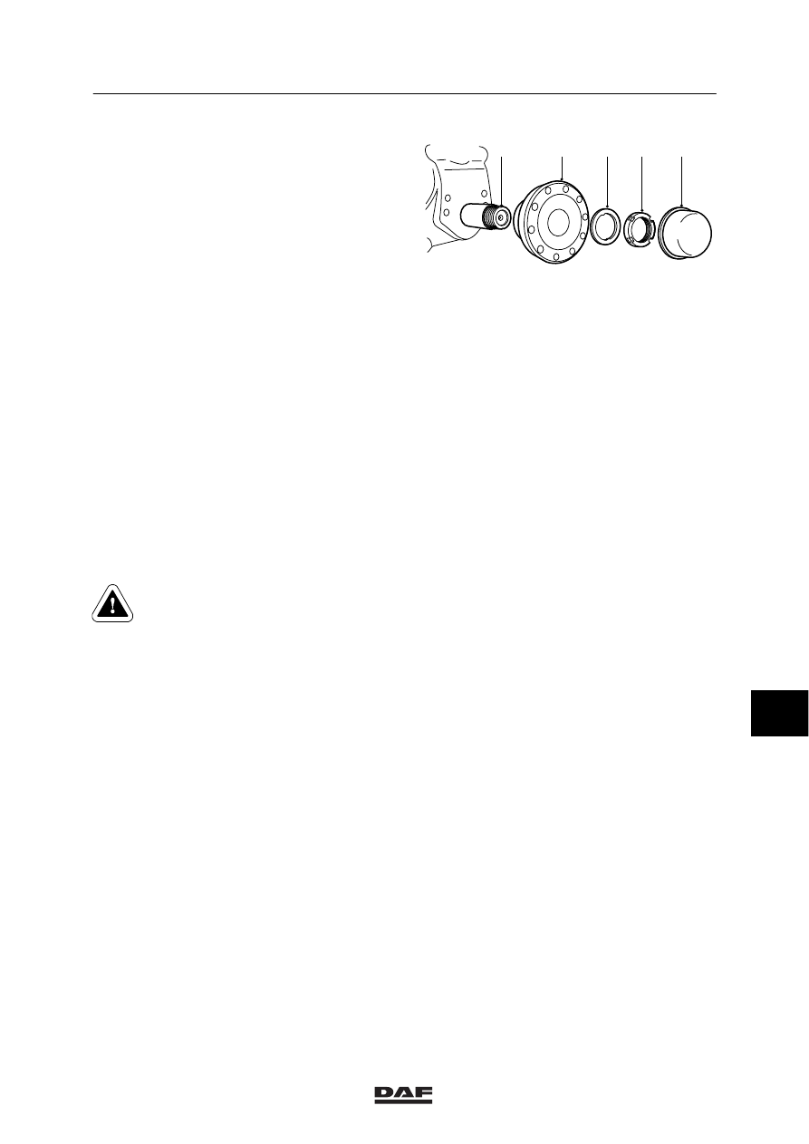
4.
Fit the compact bearing housing (4) to the
axle journal.
5.
Fit the thrust washer (3).
6.
Install a new hub nut (2). Tighten the hub
nut in the specified manner, see “Technical
data”.
Use the special tool (DAF no. 1329376) and
a torque amplifier to do so.
7.
Fit the hub cap (1).
8.
Check that the contact surfaces of the
brake disc and the compact bearing
housing are clean. Clean these if
necessary.
9.
Fit the brake disc and the wheel hub.
10. Fit the brake calliper and the brake pads.
11. Check the wheel speed sensor for smooth
operation. If the sensor is stuck, remove,
clean and refit it.
12. Press the sensor against the sensor ring by
hand.
The air gap between the sensor and the
sensor ring adjusts automatically while the
vehicle is being driven.
Never tap the sensor with a
hammer. This could damage both
the sensor and the sensor ring.
13. Fit the wheel.
14. Check the operation of the RAS-EC
system.
5
4
3
2
1
S7 00 699
9
ᓻ 200322

7
STEERED TRAILING SWIVEL AXLE
Removal and installation
LF45/55 series
3-12
3.8 REMOVAL AND INSTALLATION OF WHEEL-SPEED SENSOR RING
Removing wheel-speed sensor ring
1.
Remove the wheel speed sensor.
2.
Take the compact bearing housing off the
axle journal.
3.
Make a notch in the side of the sensor ring,
using a hammer and chisel. Make sure that
the contact surface of the sensor ring to the
compact bearing housing is not damaged in
the process.
4.
Take the sensor ring off the compact
bearing housing.
Once removed, the sensor ring
must not be reused.
Installing wheel-speed sensor ring
1.
Check the contact surface of the sensor
ring to the compact bearing housing for
damage.
2.
Check the new sensor ring carefully for
possible damage in transit.
3.
Fit a new sensor ring to the compact
bearing housing using a press and flat
plate.
4.
Check that the sensor ring makes good
contact around the entire circumference.
5.
Fit the compact bearing housing to the axle
journal.
6.
Check the wheel speed sensor for smooth
operation. If the sensor is stuck, remove,
clean and refit it.
7.
Press the sensor against the sensor ring by
hand.
The air gap between the sensor and the
sensor ring adjusts automatically while the
vehicle is being driven.
Never tap the sensor with a
hammer. This could damage both
the sensor and the sensor ring.
8.
Check the operation of the RAS-EC
system.
S7 00 700
9
ᓻ 200322
7
LF45/55 series
Removal and installation
STEERED TRAILING SWIVEL AXLE
3-13
3.9 REMOVAL AND INSTALLATION OF WHEEL-SPEED SENSOR
Removing wheel-speed sensor
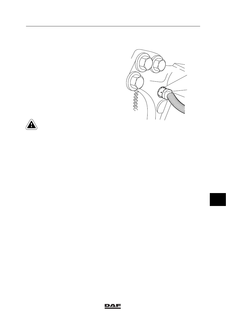
1.
Remove the wheel-speed sensor (2).
Installing wheel-speed sensor
1.
Clean the wheel-speed sensor (2) and its
holder (1). Replace the holder if necessary.
2.
Apply the specified anti-corrosion agent to
the circumference of the wheel-speed
sensor, see “Technical data”.
3.
Fit the wheel speed sensor. Press the
sensor against the sensor ring by hand.
4.
The air gap between the sensor and the
sensor ring is adjusted automatically while
the vehicle is being driven.
Never tap the sensor with a
hammer. This could damage both
the sensor and the sensor ring.
5.
Check the operation of the RAS-EC
system.
2
1
S7 00 880
9
ᓻ 200322
7
STEERED TRAILING SWIVEL AXLE
Removal and installation
LF45/55 series
3-14
3.10 REMOVAL AND INSTALLATION OF TRAILING AXLE ASSEMBLY
Removing trailing axle assembly
1.
Engage the vehicle’s parking brake and
place chocks at the front wheels.
2.
Remove the brake chamber hoses and the
disc brakes cables.
3.
Take the connector off the trailing axle
angle sensor.
4.
Remove the angle sensor control rod on the
swivel axle side.
5.
Remove the steering cylinder.
6.
Remove the stabiliser bar.
7.
Loosen the wheel nuts at both ends of the
axle, but do not remove these yet.
8.
Jack up the vehicle until the wheels are off
the ground and place suitable stands under
the chassis.
9.
Remove the wheel nuts and take the
wheels off the axle.
10. Support the axle securely and remove the
U-bolt nuts.
11. Remove the axle.
9
ᓻ 200322
Нет комментариевНе стесняйтесь поделиться с нами вашим ценным мнением.
Текст