DAF LF45, LF55 Series. Manual — part 339

5
LF45/55 series
Description of components
COMPONENTS
2-1
2. DESCRIPTION OF COMPONENTS
2.1 INDUCTIVE SENSOR
The vehicle has a number of inductive sensors,
such as:
-
wheel speed sensor
-
engine speed sensor
-
camshaft sensor
Registering engine speed
The engine speed is registered via the
crankshaft position sensor.
The crankshaft position sensor output signal is a
sine-wave signal with a frequency
corresponding to the number of holes in the
pulse disc and the crankshaft rotation frequency.
In the engine management electronic unit, the
signal is converted into a message, which is
sent via the CAN network. The VIC sends this
message to the DIP, which then activates the rev
counter.
i400442
1
2
3
Engine speed sensor operating principle
The inductive sensor consists of a permanent
magnet (1), a core (2) and a coil (3).
When the inductive sensor is situated between
two teeth, the lines of force of the magnetic field
will run directly from the north pole to the south
pole via the housing.
The moment a tooth approaches the inductive
sensor, the lines of force of the magnetic field
will run from the north pole to the south pole via
the housing, the teeth of the toothed wheel and
the core.
As more lines of force are now running through
the core, a more powerful magnetic field is
obtained.
As a result of this change in the magnetic field,
an AC voltage is generated in the coil.
The value of the AC voltage generated depends
on the speed of rotation of the toothed wheel
and the air gap between sensor (core) and
tooth.
N
S
1
2
3
W 5 01 005
2
200440
5
COMPONENTS
Description of components
LF45/55 series
2-2
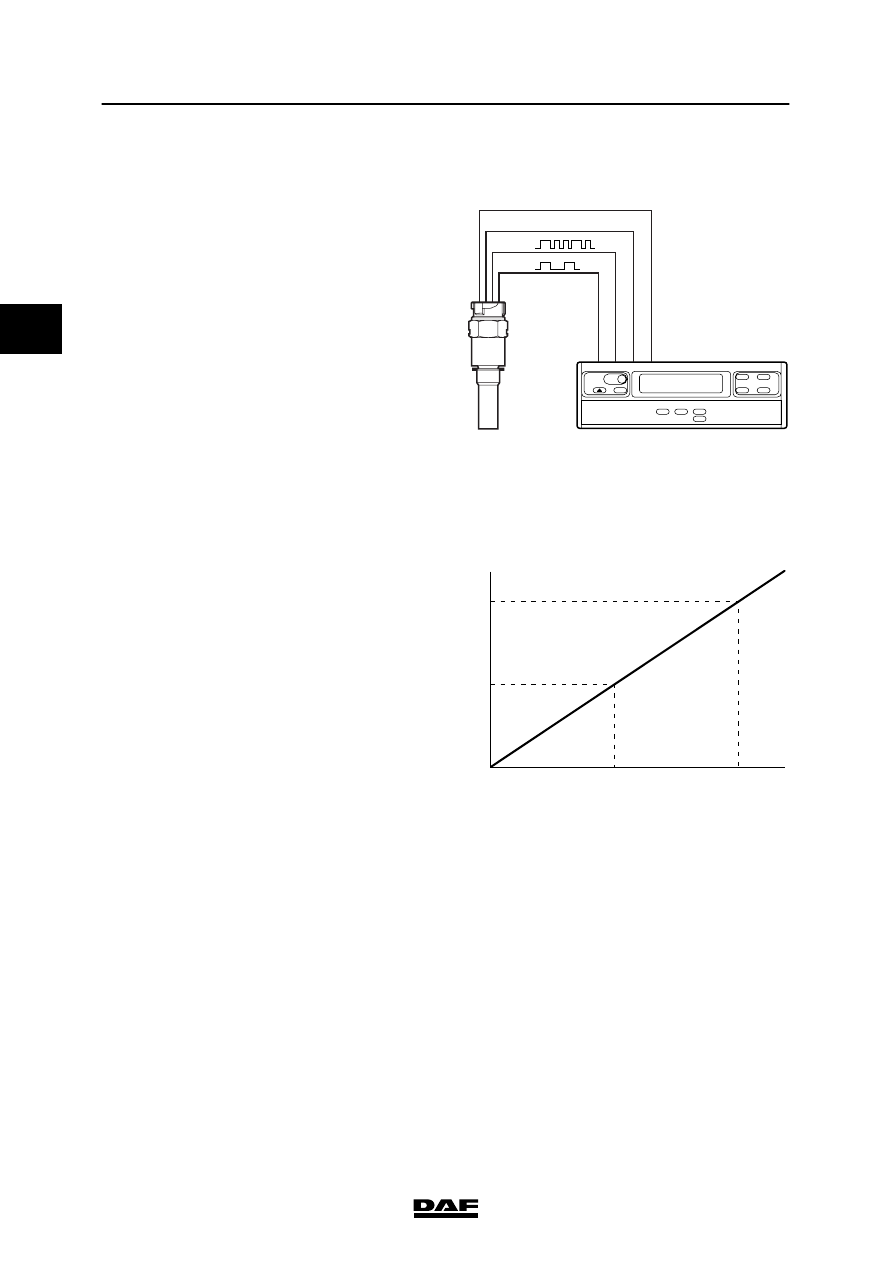
2.2 VEHICLE SPEED SENSOR
The vehicle speed sensor has two connections
for output signals. The real-time speed signal,
triggered by a Hall IC, is sent via the first
connection,
Via the other connection, a data signal
(bi-directional signal) is sent, which involves an
exchange of data between the MTCO and the
speed sensor. The MTCO requests data from
the sensor.
The sensor sends the coded data to the MTCO
in sequence, and the MTCO checks the
accuracy of this data.
The coded signal consists of the following data:
-
serial number of the sensor
-
Master key (the same as that of the MTCO)
-
coded speed signal
In the MTCO, the coded speed signal is
compared with the real-time speed signal.
The MTCO sends commands and data to the
sensor at 10-second intervals.
1
2
M
-
+
4.
3.
2.
1.
-
+
E501055
Duty cycle speed signal
The speed signal sent via the vehicle speed
sensor to the MTCO is processed by the MTCO
and sent as a message via the CAN network.
The speed signal is also converted into a
duty cycle signal. This duty cycle signal is used
by the electronic units that do not receive the
speed signal message via the CAN network.
The diagram alongside shows the linear
characteristic of the duty cycle (%) in relation to
the vehicle speed (V).
This graph applies to all vehicle models.
Inspection
The duty cycle signal (square-wave voltage) can
be checked with a multimeter that is set to the
DC voltage or duty cycle range or with a
scopemeter.
44
22
50
100
V(km/h)
%
E501057
2
200440
5
LF45/55 series
Description of components
COMPONENTS
2-3
2.3 TEMPERATURE SENSORS
The vehicle has a number of temperature
sensors, such as:
-
coolant temperature sensor
-
inlet air temperature sensor
-
fuel temperature sensor
-
ambient air temperature sensor
These sensors are temperature-sensitive
resistors.
The resistance of these sensors changes
considerably with rises or drops in temperature.
There are two types of temperature sensor:
-
NTC resistor (Negative
Temperature Coefficient)
-
PTC resistor (Positive
Temperature Coefficient).
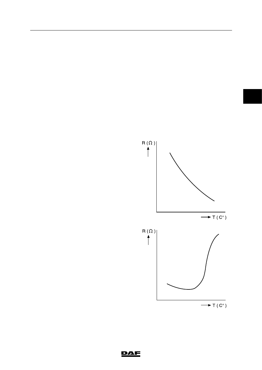
NTC resistor
In an NTC resistor, the resistance value reduces
as the temperature rises.
Application:
-
measuring coolant temperature.
W 5 01 010
PTC resistor
In a PTC resistor, the resistance value increases
as the temperature rises.
In the PTC resistor, in contrast to the
NTC resistor, there will be a great change in
resistance within a small temperature range.
Application:
-
measuring air temperature when cab heater
is on.
Inspection
The temperature sensors can be checked using
a multimeter that is set to the resistance range.
W 5 01 011
2
200440
5
COMPONENTS
Description of components
LF45/55 series
2-4
2.4 PRESSURE SENSORS
The vehicle has a number of pressure sensors,
such as:
-
pressure sensor to register the bellows
pressure in ECAS.
-
pressure sensor on the air supply unit for
pressure gauges in the DIP-4.
There is a diaphragm made of semiconducting
material (silicon) in the pressure sensor.
When pressure is applied to the diaphragm, it
will be deflected.
Deflection of the diaphragm leads to a change in
the resistance of the semiconducting material.
The diaphragm is part of what is known as a
bridge circuit.
Deflection of the diaphragm unbalances the
bridge circuit, which changes the output signal.
The output voltage is in direct proportion to the
pressure applied (deflection of the diaphragm).
Inspection
The output voltage can be checked using a
multimeter set to the DC voltage range.
V
W 5 01 012
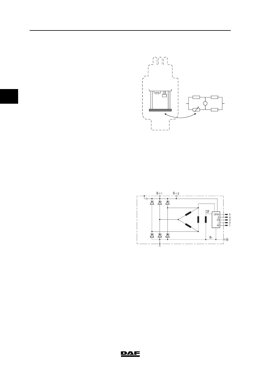
2.5 ALTERNATOR
The compact alternator is a lightweight
alternator with two internal cooling fans. The
electronic controller also controls pre-excitation
of the alternator. The function of the exciter
diodes has also been taken over by the
controller. The alternator generates high
currents in the lower speed range.
S
sens connection of the regulator
15
power supply after contact
L
connection to VIC
The alternator has two B+ connections that are
connected to each other internally. B+1 is
connected to the batteries and the B+2
connection is connected to the “S” connection
on the regulator. B-- (earth) is connected to the
alternator housing.
E501373
2
200440
Нет комментариевНе стесняйтесь поделиться с нами вашим ценным мнением.
Текст