DAF LF45, LF55 Series. Manual — part 288
©
200416
2-5
General
BE ENGINE FUEL SYSTEM
ΛΦ45/55 series
4
2
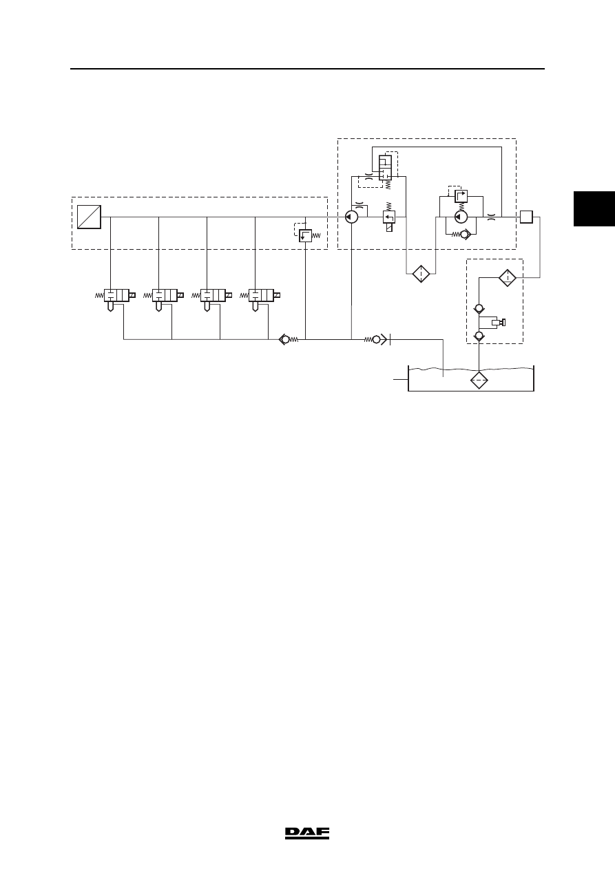
2.2 SYSTEM DESCRIPTION, ECS-DC3 FUEL SYSTEM
The fuel lift pump (4a) draws the fuel from the fuel
tank (1) through the cooling plate (2) of the
electronic unit (3).
The purpose of the cooling plate (3) is to ensure
that the electronic unit does not become too hot.
The fuel lift pump (4a) is fitted against the high-
pressure pump (4c) and is driven by the camshaft
gear.
From the fuel lift pump, fuel is forced towards the
fuel fine filter (5).
After the filter, the fuel enters the high-pressure
pump (4c) via the fuel pump control solenoid
valve (4b), which controls the amount of fuel
going to the high-pressure pump. Fuel not taken
in by the high-pressure pump returns via the by-
pass valve (4d) to the fuel lift pump supply pipe
and part of it is used for lubricating the high-
pressure pump.
The high-pressure pump forces the fuel under
high pressure to the fuel rail (6). The fuel rail
distributes the fuel among the injectors (7). The
fuel rail (6) also functions as an accumulator to
ensure that large fluctuations in pressure,
resulting from injector openings and pump
pressure pulses, are prevented as much as
possible.
4
5
6
7
8
9
7
7
a
a
b
b
b
a
c
d
7
3
2
1
I400828
U
P
BE ENGINE FUEL SYSTEM
2-6
©
200416
General
2
ΛΦ45/55 series
4
The pressure in the fuel rail is registered by the
rail pressure sensor (6a). The electronic unit uses
this data to control the high-pressure pump (via
the fuel pump control solenoid valve), so that the
rail pressure can be kept at the desired level. The
desired pressure is not constant, but depends on
the operating conditions.
A pressure relief valve (6b) is fitted at the end of
the fuel rail. If the pressure in the fuel rail rises too
high (in emergencies only), this valve ensures
that the excess fuel flows back to the return pipe.
The return pipe is connected with the return pipe
to the fuel tank (1).
The electronic unit uses the present rail pressure
to calculate the time during which the injector
needs to be opened in order to obtain the desired
injection quantity.
A pressure relief valve (8) connects the injector
leak-off ducts in the cylinder head with the return
pipe to the fuel tank (1). This pressure relief valve
prevents the fuel from flowing out of the injectors
when the engine has stopped running.
If the system has been "open", the fuel system
can be bled using the primer pump (2a), which is
integrated in the water separator/coarse filter
(2b).
The return pipe to the tank contains a check valve
(9), which is normally closed. As soon as the
quick release coupling on the fine filter head is
disconnected, the return pipe closes so that it
cannot empty.
©
200416
2-7
General
BE ENGINE FUEL SYSTEM
ΛΦ45/55 series
4
2
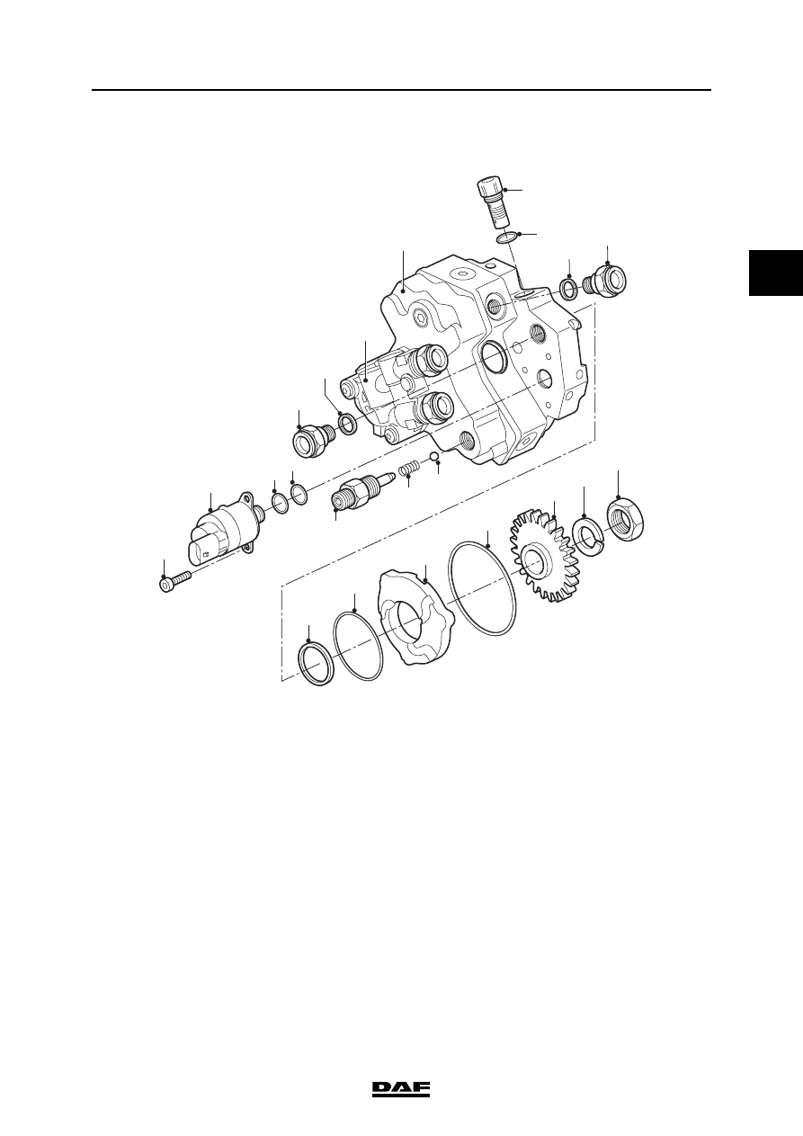
2.3 OVERVIEW DRAWING, FUEL PUMP
1.
Attachment bolt
2.
Fuel pump control solenoid valve
3.
O-ring
4.
O-ring
5.
Fuel pipe connection
6.
Copper ring
7.
Lift pump
8.
High-pressure pump
9.
Circulation valve
10. O-ring
11. Copper ring
12. Fuel pipe connection
13. High-pressure pipe connection
14. Spring
15. Ball
16. Oil seal
17. O-ring
18. Adapter ring
19. O-ring
20. Gear wheel
21. Sealing ring
22. Nut
17
16
18
19
20
13
14
15
2
3
4
1
5
7
8
6
21
9
10
11
12
22
i400766
BE ENGINE FUEL SYSTEM
2-8
©
200416
General
2
ΛΦ45/55 series
4
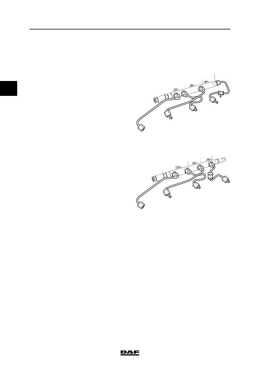
2.4 OVERVIEW DRAWING, FUEL RAIL
Overview drawing, fuel rail, < production date
2003-49 (chassis number < 0L253643)
The figure shows the connections to the injector
pipes. The numbers indicate the cylinder number
of the connection.
Overview drawing, fuel rail, production date
2003-49 (chassis number 0L253643)
The figure shows the connections to the injector
pipes. The numbers indicate the cylinder number
of the connection.
3
4
1
2
i400764
3
4
1
2
i400873
Нет комментариевНе стесняйтесь поделиться с нами вашим ценным мнением.
Текст