DAF LF45, LF55 Series. Manual — part 248
©
200508
4-3
Removal and installation
ZF 6S-850 GEARBOX
ΛΦ45/55 series
3
5
4.2 REMOVING AND INSTALLING GEARBOX, CE ENGINE
Removing gearbox, CE engine
1.
Disconnect the earth lead from the battery
terminal.
2.
Remove the attachment bolts of the prop
shaft flange and remove the prop shaft.
3.
If present, remove the attachment bolts from
the intermediate bearing.
4.
Remove the attachment bolt from the
exhaust bracket on the gearbox.
5.
Remove the clamping strip from the exhaust
pipe.
6.
Remove the attachment bolt of the rubber
suspension point on the end of the exhaust.
7.
Twist the end-pipe of the exhaust loose and
remove it.
8.
Remove the attachment bolts from the clutch
cylinder and remove it.
9.
Mark all the electrical connectors and
remove them.
10. Remove the compressor pipe bracket.
11. Remove the selector rod from the adjusting
mechanism in such a manner that the
settings are not changed.
12. Support the gearbox and remove the
attachment bolts around it.
13. Manoeuvre the gearbox to the rear until it is
free and then remove it.
ZF 6S-850 GEARBOX
4-4
©
200508
Removal and installation
5
ΛΦ45/55 series
3
Installing gearbox, CE engine
1.
Engage the highest gear in order to align the
keys of the input shaft with the clutch plate.
2.
Fit the gearbox onto the engine. If
necessary, rotate the prop shaft flange in
order to align the keys.
3.
Fit the gearbox attachment bolts all around
and tighten them to the specified torque. See
"Technical data".
4.
Install the selector rod on the adjusting
mechanism. Use new self-locking nuts.
5.
Fit the exhaust bracket.
6.
Install the compressor pipe bracket.
7.
Fit the electronic connectors onto the
gearbox.
8.
Fit the clutch cylinder.
9.
Install the exhaust pipe, fasten it with the
clamping strap and fit the attachment bolt of
the suspension rubber.
10. Install the prop shaft intermediate bearing, if
it has been removed, and tighten the bolts by
hand.
11. Fit the prop shaft flange onto the gearbox.
Tighten the attachment bolts to the specified
torque. See "Technical data".
12. Tighten the intermediate bearing attachment
bolts to the specified torque. See "Technical
data".
13. Check the oil level. See "Inspection and
adjustment".
14. Fit the silencer cap.
15. Fit the earth lead to the battery terminal.
Note:
If a gearbox of a different type is mounted, or a
gearbox with a different reduction, this should be
reported. If the correct data are present, they can
be input into the VIC using DAVIE XD.
©
200508
4-5
Removal and installation
ZF 6S-850 GEARBOX
ΛΦ45/55 series
3
5
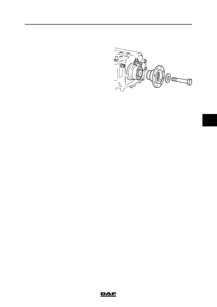
4.3 REMOVAL AND INSTALLATION, DRIVE FLANGE
Removing the drive flange
1.
Make a reference mark on the prop shaft and
flange.
2.
Detach the prop shaft from the flange and
secure it.
3.
Fit special tool (DAF no. 0484977) to hold
the flange in place.
4.
Remove the attachment bolt and washer.
5.
Using special tool (DAF no. 0484978),
remove the drive flange from the shaft.
Installing the drive flange
1.
Heat the drive flange to a temperature of
max. 120
″C.
2.
Oil the output shaft lightly and slide the drive
flange over the shaft in its correct position.
3.
Fit the special tool (DAF no. 0484977) onto
the drive flange.
4.
Tighten the attachment bolt to the specified
torque. See "Technical data".
5.
Fit the prop shaft. Tighten the attachment
bolts to the specified torque. See "Technical
data".
V3 00 416
ZF 6S-850 GEARBOX
4-6
©
200508
Removal and installation
5
ΛΦ45/55 series
3
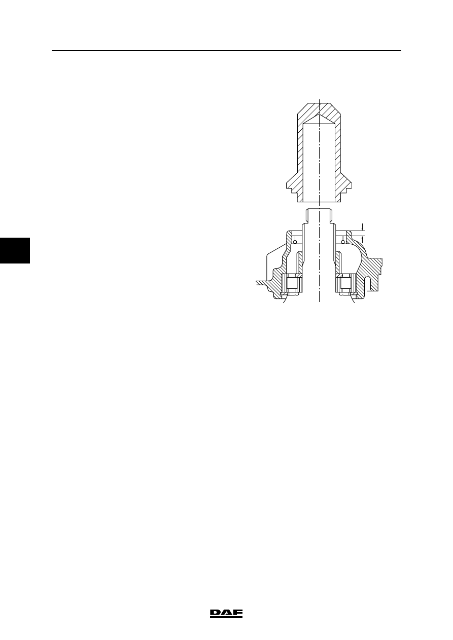
4.4 REMOVAL AND INSTALLATION, OUTPUT SHAFT OIL SEAL
Removing output shaft oil seal
1.
Remove the drive flange.
2.
Pull the oil seal from the gearbox housing
using special tool (DAF no. 0484899).
Installing output shaft oil seal
1.
Check the axial play of the output shaft. See
"Technical data".
2.
Around the oil seal, clean the gearbox
housing without letting dirt into the gearbox.
3.
Apply a small amount of liquid gasket to the
outside of oil seals fitted with a steel cover.
Apply a small amount of green soap to the
outside of oil seals fitted with a rubber cover.
4.
Fit the oil seal in the gearbox housing using
special tool (DAF no. 0694816). The tool will
position the oil seal at the correct depth in the
housing.
5.
Fit the drive flange.
W 3 03 048
7 mm
Нет комментариевНе стесняйтесь поделиться с нами вашим ценным мнением.
Текст