DAF LF45, LF55 Series. Manual — part 423
11
200440
2-33
Changes in the electrical system from chassis number 0L247507
5
CHANGES IN THE ELECTRICAL SYSTEM
LF45/55 series
11
10.
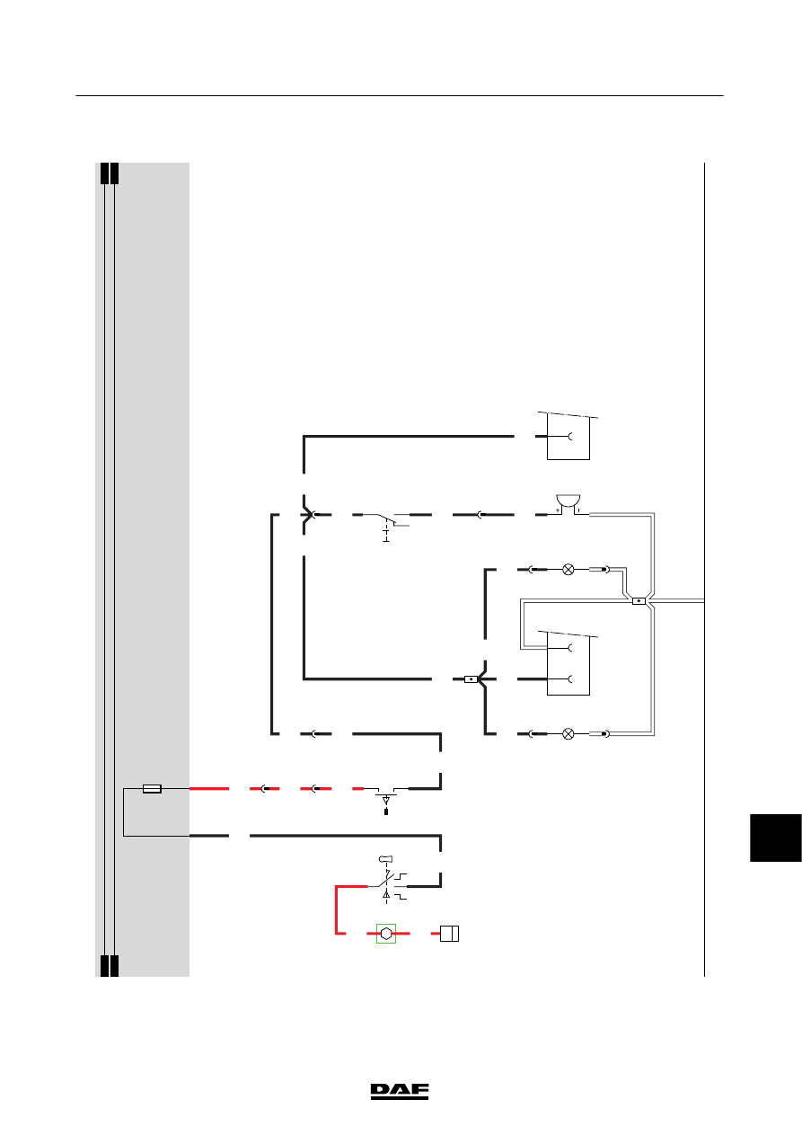
REVERSING
LIGHTS/BUZZER
When
the
contact
is
switched
on,
power
is
supplied
to
the
reversing
light
switch
(E501)
via
E
018
and
wire
1217.
This
switch
is
mounted
in
the
gearbox.
T
he
contacts
are
closed
w
hen
the
gearbox
is
switched
to
the
“reverse”
position.
Power
is
then
supplied
via
wire
4591
to
the
reversing
lights
(C026/C027)
and
drawn
vehicle
connector
A
001.
The
reversing
buzzer
(B176)
can
only
be
activated
via
wire
5104
if
the
dashboard
switch
(C880)
is
in
position
I.
S
witching
C880
to
the
0
position
turns
of
ft
he
reversing
buzzer
.
The
application
connector
(A070)
also
has
a
connection
that
is
switched
by
the
reversing
light
switch
(E501).
200440
2-34
5
CHANGES IN THE ELECTRICAL SYSTEM
Changes in the electrical system from chassis number 0L247507
LF45/55 series
11
10
1427090/04
EL001628
1
2
3
4
5
6
7
8
9
10
11
12
13
14
15
16
17
18
19
20
21
22
23
24
25
26
27
28
29
30
31
32
33
34
35
36
37
38
39
40
41
42
43
44
45
46
47
48
49
50
51
52
53
4001
1217
1217
4001
1217
4591
4591
4591
4591
4591
4591
5104
5104
4591
4591
4591
4591
4591
4591
4591
1000
1000
E349
1
2
B11/702
A10/702
D942
1010
1000
1010
1000
E018
15A
4001
A7
713
1
952
4
952
B2
713
A3
713
A001
31
3
765
C026
1
2
3
764
C027
1
2
G520
B176
1
2
5
71
0I
C880
1
765
1
764
C841
1/808
2/808
4/808
6/808
A070
4
F501
2
1
200440
2-35
Changes in the electrical system from chassis number 0L247507
5
CHANGES IN THE ELECTRICAL SYSTEM
LF45/55 series
11
12.
ST
OP
LIGHTS/CAB
TIL
T
ING
G
EAR
ST
OP
LIGHTS
When
stop
lights/cl
ut
ch
swit
ch
E
587
is
operated
(connection
between
contacts
4
and
3)
by
depressing
the
brake
pedal,
relay
G036
is
energised
via
wire
4602.
Power
w
ill
also
be
supplied
to
the
VIC
(pin
D
32/746).
Through
fuse
E013,
wire
1209,
contacts
3
and
5
of
relay
G036
and
wire
4601
a
voltage
is
now
applied
to
the
right
stop
light
(C021)
and
the
left
stop
light
(C020),
so
that
they
come
on.
The
lights
that
are
connected
via
drawn
vehicle
socket
A
000
will
also
come
on.
The
ECAS-3
unit
(D851)
or
ECAS-2
unit
(D802)
then
also
receives
a
signal.
Application
connector
A
070
is
also
connected
to
wire
4601.
CAB
TIL
T
ING
G
EAR
The
switch
for
the
cab
lock
(F009)
is
a
“normally
closed”
switch.
T
he
switch
is
opened
when
the
cab
is
in
the
driving
position.
When
the
cab
is
tilted,
the
switch
closes
and
pin
B
16/744
of
the
V
IC
is
connected
to
earth
via
w
ire
4312.
When
the
alarm
is
active
it
knows
that
the
cab
is
in
the
driving
position
because
a
small
current
goes
to
earth
through
the
control
switch
for
cab
tilting
(F009).
D
iode
D758
prevents
this
current
from
also
flowing
to
earth
through
the
V
IC
(the
VIC
in
sleep
mode),
in
which
case
the
alarm
w
ould
not
know
whether
the
cab
is
being
tilted
intentionally
or
by
accident.
VARIANTS
Location 13
If
the
vehic
le
is
fitted
w
ith
CDM,
see
section
diagram
32
23,28
Connector
762:
N
otf
itt
edo
nv
eh
ic
let
yp
eF
T
29
Electronic
unit,
ECAS-3
(D851):
On
a
6x2
vehicle,
E
C
A
S
-2
electronic
unit
D
802
(7/340)
200440
2-36
5
CHANGES IN THE ELECTRICAL SYSTEM
Changes in the electrical system from chassis number 0L247507
LF45/55 series
Нет комментариевНе стесняйтесь поделиться с нами вашим ценным мнением.
Текст