DAF LF45, LF55 Series. Manual — part 428
11
24
1427090/04
EL001639
107
108
109
110
111
112
113
114
115
116
117
118
119
120
121
122
123
124
125
126
127
128
129
130
131
132
133
134
135
136
137
138
139
140
141
142
143
144
145
146
147
148
149
1
50
151
152
153
154
155
156
157
158
159
4006
5628
110
111
112
4596
3718
4006
5628
110
111
112
4596
3718
D942
1010
1000
1010
1000
D936
B6/
853
B8/
853
B10/
853
B11/
853
B12/
853
B19/
853
B21/
853
1
2
3
4
5
6
7
8
A096
!
200440
2-53
Changes in the electrical system from chassis number 0L247507
5
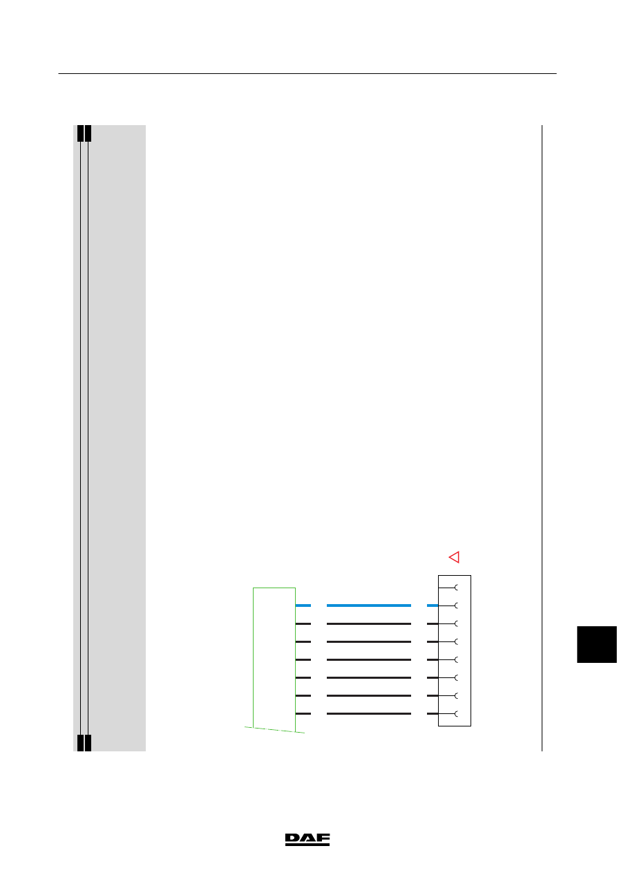
CHANGES IN THE ELECTRICAL SYSTEM
LF45/55 series
11
25.
AGC
AUT
OMA
T
IC
GEARBOX
(MD3060)
Power
supply
before
contact
is
obtained
directly
from
the
batteries
(A500)
via
w
ire
336
and
a
10
A
fuse
(MAIN)
in
the
V
IM
(D822,
pins
J1
and
J2).
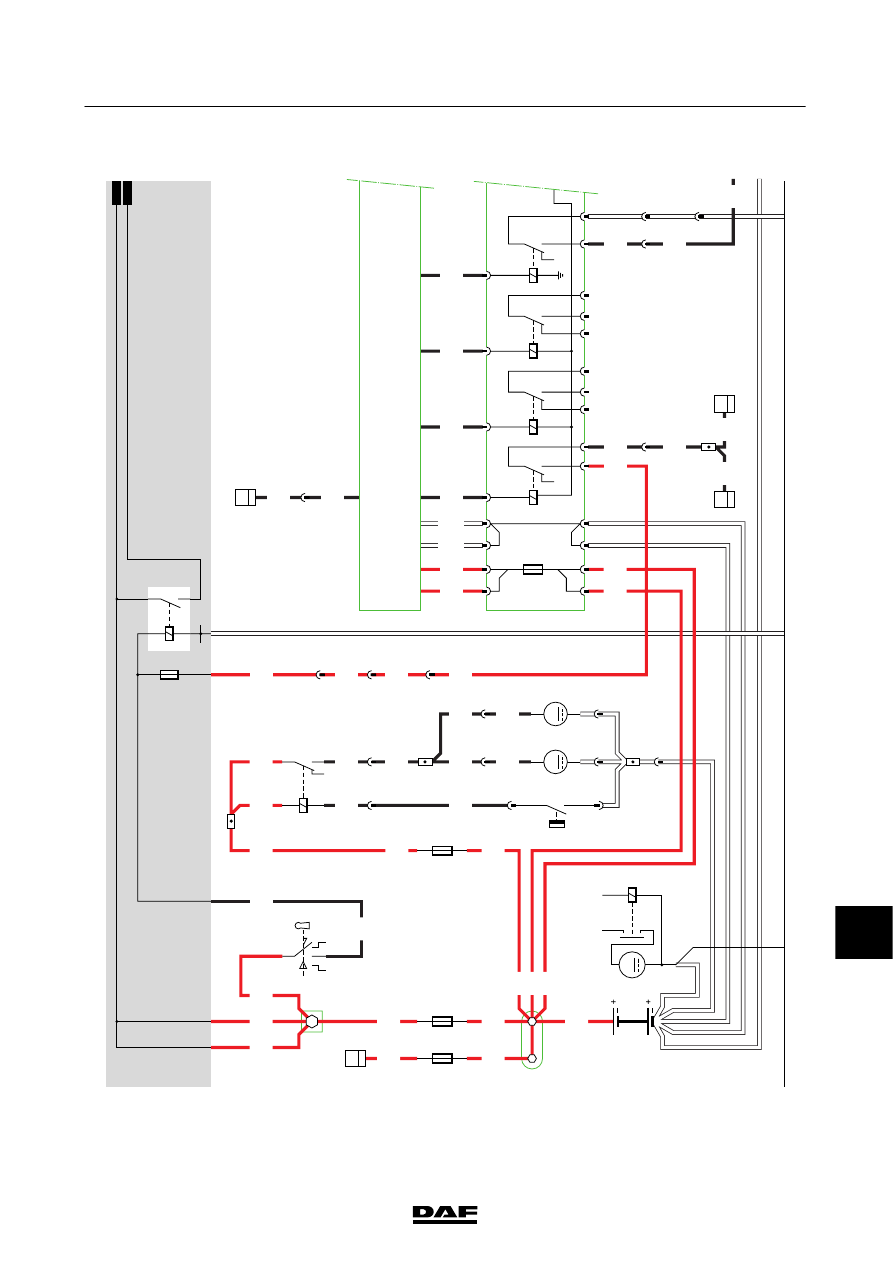
The
electronic
unit
(D866)
receives
voltage
before
contact
at
pin
V1/907
and
V16/907
from
the
V
IM
(D822,
pins
R1
and
R2)
via
wires
1164.
V
oltage
after
contact
is
obtained
via
fuse
E279
and
wire
121
1.
Wire
121
1
is
connected
directly
to
electronic
unit
D
866
(pin
S4/905).
T
hew
irea
ls
or
un
s
to
th
eV
IM
(p
in
C
1)a
nd
various
relays
in
de
VIM
are
supplied
w
ith
voltage
after
contact
via
a
10
A
fuse
(IGN).
The
voltage
after
contact
can
also
be
found
in
the
diagnostic
socket
for
the
automatic
gearbox
(A032).
The
earth
connections
are
connected
directly
to
the
earth
side
of
the
batteries
(A500)
and
also
run
to
the
electronic
unit
(D866)
via
the
VIM
(pins
K1
and
K2).
The
elect
rical
syst
em
of
th
e
aut
omat
ic
gearbox
is
almost
completely
located
on
the
chassis. Connections
leading
into
the
cab
are
provided
for
a
number
of
VIC
functions:
-
fault
m
essages
from
the
automatic
gearbox
(S31/905)
to
the
V
IC
unit
(D900)
-
C
AN
connections
(S13/905
and
S29/905)
to
the
V
IC
unit
(D900)
-
V
ehicle
interface
module
(D822,
pin
F
1)
to
the
V
IC
unit
(D900)
Diagnosis
of
the
automatic
gearbox
takes
place
via
the
C
AN
network,
w
hich
is
connected
to
the
diagnostic
socket
(A032)
and
the
V
IC
unit
(D900).
Note: Where
an
automatic
gearbox
is
fitted,
there
are
two
dashboard
lead-through
connectors,
716.
One
connector
is
occupied
by
spare
wiring
(see
application
connectors)
and
the
other
has
3
occupied
positions
(A1,
wire
3458;
A3,
w
ire
123;
and
A4,
w
ire
4614),
only
one
of
which
is
connected.
The
716
with
the
spare
w
iring
is
not
then
connected
and
hangs
loose
near
the
dashboard
lead-through.
200440
2-54
5
CHANGES IN THE ELECTRICAL SYSTEM
Changes in the electrical system from chassis number 0L247507
LF45/55 series
11
25
1427090/04
EL001640
1
2
3
4
5
6
7
8
9
10
11
12
13
14
15
16
17
18
19
20
21
22
23
24
25
26
27
28
29
30
31
32
33
34
35
36
37
38
39
40
41
42
43
44
45
46
47
48
49
50
51
52
53
4001
1000
1000
1000
1000
1000
1000
1000
1000
336
336
336
336
1000
1000
1164
1164
5655
21WT
12WT
5649
5705
4006
4591
4591
4591
4591
4721
4721
1217
1217
1217
1217
1217
4614
4614
4001
4721
1637
1637
1637
1637
5720
5720
5720
5720
5720
5720
5721
5721
A10/702
A11/702
E349
80A
2
1
E286
125A
2
1
E354
25A
2
1
1/705
2/705
C841
1/808
2/808
4/808
6/808
G014
1
5
C027
1
10
C026
1
10
A7
713
1
952
10
829
5
829
3
829
4
829
2
952
2
829
B11/702
D942
1010
4001
G015
3
1
24
M
1010
1000
1000
E018
15A
D961
A8
21
D866
V27/
907
V1/
907
V16/
907
V17/
907
V32/
907
V4/
907
V2/
907
V3/
907
V6/
907
MAIN
10A
2
1
G350
3
2
14
5
A1
B1
J2
S2
R2
J1
R1
K2
L2
K1
L1
G294
3
2
14
5
A3
A2
B2
S3
SF02
3
2
14
5
E3
E2
D2
M1
G185
3
1
24
5
F1
G1
P1
VIM18
D822
VIM30
B399
M
1
2
B400
M
1
2
1
847
1
844
1
845
1
848
2
844
2
847
2
848
1
846
2
846
2
1
E597
G444
1
24
5
3
A500
50
30
B010
M
31
200440
2-55
Changes in the electrical system from chassis number 0L247507
5
CHANGES IN THE ELECTRICAL SYSTEM
LF45/55 series

11
25
1427090/04
EL001641
54
55
56
57
58
59
60
61
62
63
64
65
66
67
68
69
70
71
72
73
74
75
76
77
78
79
80
81
82
83
84
85
86
87
88
89
90
91
92
93
94
95
96
97
98
99
100
101
102
103
104
105
106
3458
1211
1211
1211
1211
5689
5690
1211
5689
5690
3458
3458
4721
2170
2170
2170
3701E
3700E
3701E
3700E
3701E
3700E
3700E
3701E
3701E
3700E
4721
1211
1211
1211
1211
6034
5701
3662
1211
1211
3700E
3701E
3700E
3701E
8
829
A1
716
8
720
1
829
1
724
2
724
6
850
5
850
2
850
3
850
1
850
B13/
744
C2/
745
C1/
745
C20/
745
C49/
745
D900
T
857
V
857
1
849
A032
A
B
C
F
G
D
120
Ω
A5/701
D942
1010
1000
1010
1000
E035
10A
D866
S4/
905
S1/
905
S17/
905
S13/
905
S29/
905
S31/
905
V18/
907
V22/
907
V20/
907
IGN
10A
2
1
4
C2
SF04
3
2
14
5
E1
F3
F2
D1
C1
N2
SF03
3
1
H2
25
P2
M2
VIM18
D822
VIM30
D867
T
V
829
6
829
7
850
4
200440
2-56
5
CHANGES IN THE ELECTRICAL SYSTEM
Changes in the electrical system from chassis number 0L247507
LF45/55 series
Нет комментариевНе стесняйтесь поделиться с нами вашим ценным мнением.
Текст