DAF LF45, LF55 Series. Manual — part 153

©
200505
4-5
CE engine
TECHNICAL DATA
ΛΦ45/55 series
2
0
Flywheel/starter ring gear
Flywheel housing
Vibration damper
M201199
A
B
Radial run-out,
measured on the
inside of the flywheel
outer edge (A).
max. 0.127 mm
Axial deviation,
measured on the
flywheel outer edge
(B).
max. 0.406 mm
Heat starter ring gear
(max. 20 min.)
max. 125
C
Fit flywheel housing using sealant
Loctite 5205
Difference in thickness at 4 places must not
exceed:
6.35 mm
TECHNICAL DATA
4-6
©
200505
CE engine
0
ΛΦ45/55 series
2
4.2 TIGHTENING TORQUES
The tightening torques stated in this section are
different from the standard tightening torques
stated in the overview of the standard tightening
torques. The other threaded connections not
specified must therefore be tightened to the
torque stated in the overview of standard
tightening torques.
When attachment bolts and nuts are replaced, it
is important that - unless stated otherwise - these
bolts and nuts are of exactly the same length and
property class as those removed.
Starter motor
Automatic poly-V-belt tensioner
Alternator
Air compressor
Steering pump
Air-conditioning compressor
Valve gear
Attachment bolts
43 Nm
Attachment bolts
43 Nm
Alternator bracket attachment bolts
30 Nm
Alternator attachment bolts
60 Nm
Pulley attachment nut
80 Nm
Compressor attachment nuts
80 Nm
Pipe attachments
39 Nm
Attachment bolts, steering pump
55 Nm
Line connection in the pump, delivery side
36 Nm
Attachment bolts, cover
20 Nm
Attachment bolts, reservoir
8 Nm
Compressor support attachment bolts
30 Nm
Compressor attachment bolts
60 Nm
Rocker setting bolt lock nut
24 Nm
Valve sleeve attachment bolts
24 Nm
Valve cover attachment bolts
10 Nm
Rocker seat attachment bolts
36 Nm
Injector wiring
1 Nm
©
200505
4-7
CE engine
TECHNICAL DATA
ΛΦ45/55 series
2
0
Intake manifold
Exhaust manifold
(1) Tighten crosswise from inside to outside.
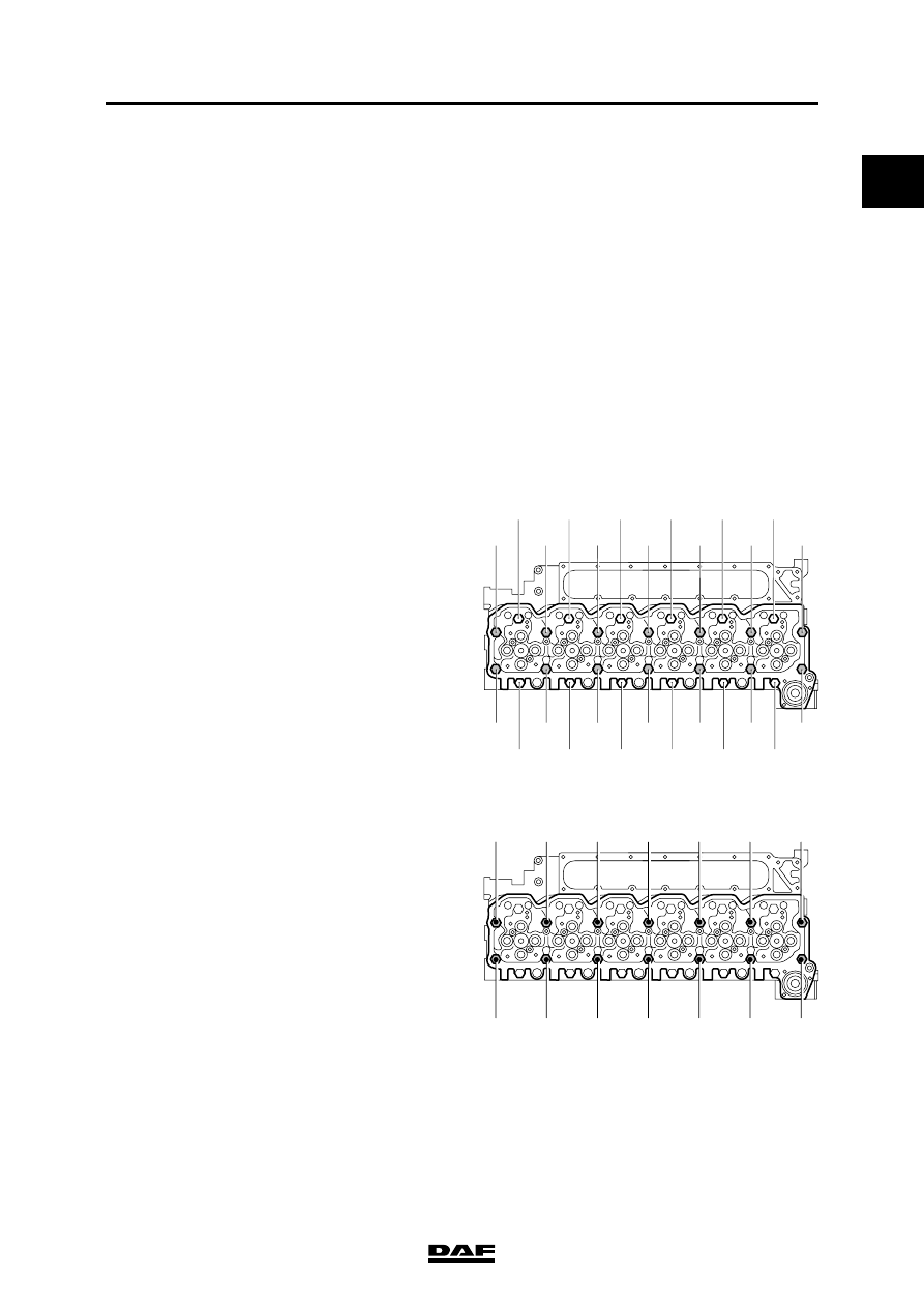
Cylinder head
Note:
Apply a drop of engine oil on the thread of the
attachment bolts and under the bearing surface
of the bolt heads.
Phase 1
(1) Tighten the bolts in the order indicated
Phase 2
(1) Tighten the bolts in the order indicated
Intake manifold attachment bolts
24 Nm
Fuel rail attachment bolts
24 Nm
Glow element attachment bolts
14 Nm
Air inlet hose clamps
7 Nm
Attachment bolts
43 Nm
Heat shields
56 - 64 Nm
M201143
4
5
13
21
9
17
8
7
3
6
14
22
2
10
18
26
1
25
20
12
24
23
19
11
15
16
All attachment bolts
35 Nm
M201202
12
11
8
7
4
3
1
2
5
6
9
10
13
14
Use only attachment
bolts that are
150 mm in length
55 Nm

TECHNICAL DATA
4-8
©
200505
CE engine
0
ΛΦ45/55 series
2
Phase 3
(1) Tighten the bolts in the order indicated
Vibration damper
Timing gear
Front engine panel
(1) Tighten the attachment bolts in the order indicated
Flywheel
M201143
4
5
13
21
9
17
8
7
3
6
14
22
2
10
18
26
1
25
20
12
24
23
19
11
15
16
All attachment bolts
2 steps of 90
angular
displacement
each
Attachment bolts
1
st
phase
50 Nm
2
nd
phase
90
angular displacement
Camshaft locking plate attachment bolts
24 Nm
M8 attachment bolts for timing gear case
24 Nm
M10 attachment bolts for timing gear case
47 Nm
M12 attachment bolts for timing gear case
50 Nm
Camshaft gear attachment bolts
36 Nm
M201144
1
12
9
6
3
8
5
2
4
7
11
10
13
Front engine panel
attachment bolts
24 Nm
Attachment bolts
30 Nm + 60
angular displacement
Нет комментариевНе стесняйтесь поделиться с нами вашим ценным мнением.
Текст