Dodge Dakota (ND). Manual — part 148
B1428-REMOTE RADIO SWITCH INPUT CIRCUIT STUCK (CONTINUED)
For a complete wiring diagram Refer to Section 8W.
•
When Monitored:
With the ignition in any position except off.
•
Set Condition:
The Instrument Cluster detects a stuck switch state on the (X20) Radio Control MUX circuit for more than 30
seconds.
Possible Causes
(X20) REMOTE CONTROL MUX CIRCUIT SHORT TO GROUND
(X20) REMOTE CONTROL MUX CIRCUIT SHORT TO (G902) SWITCH MUX RETURN CIRCUIT
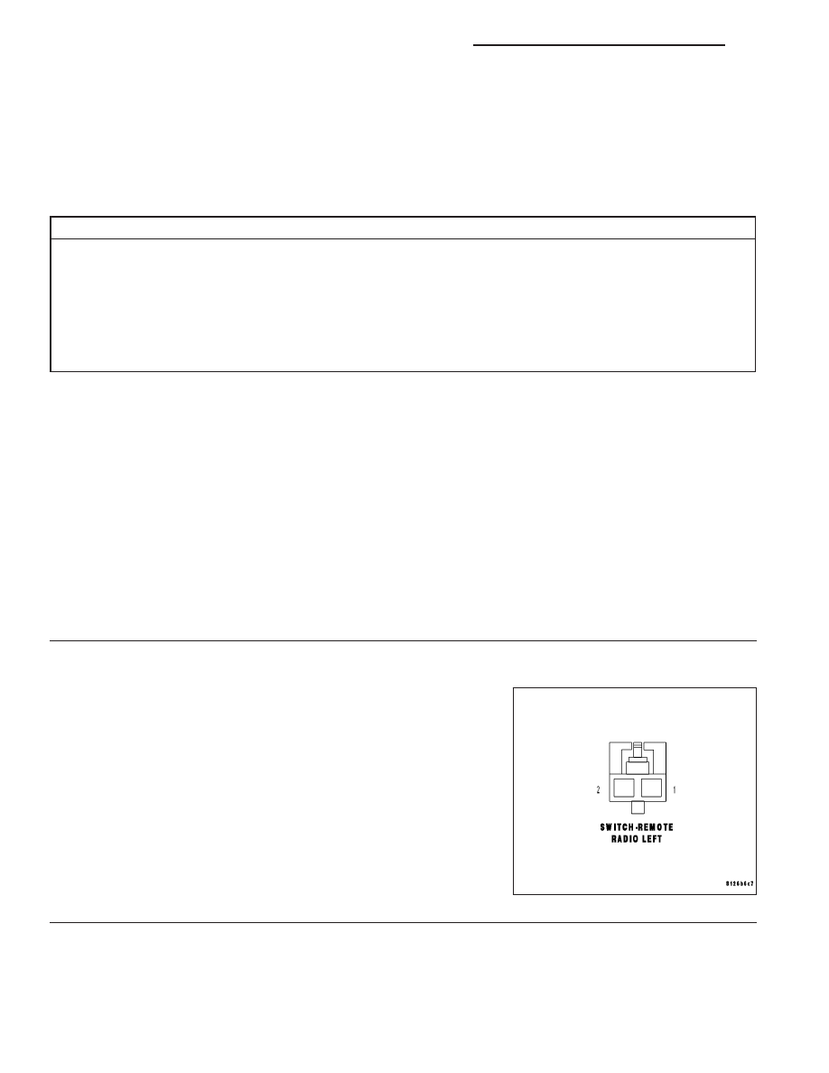
LEFT REMOTE RADIO SWITCH
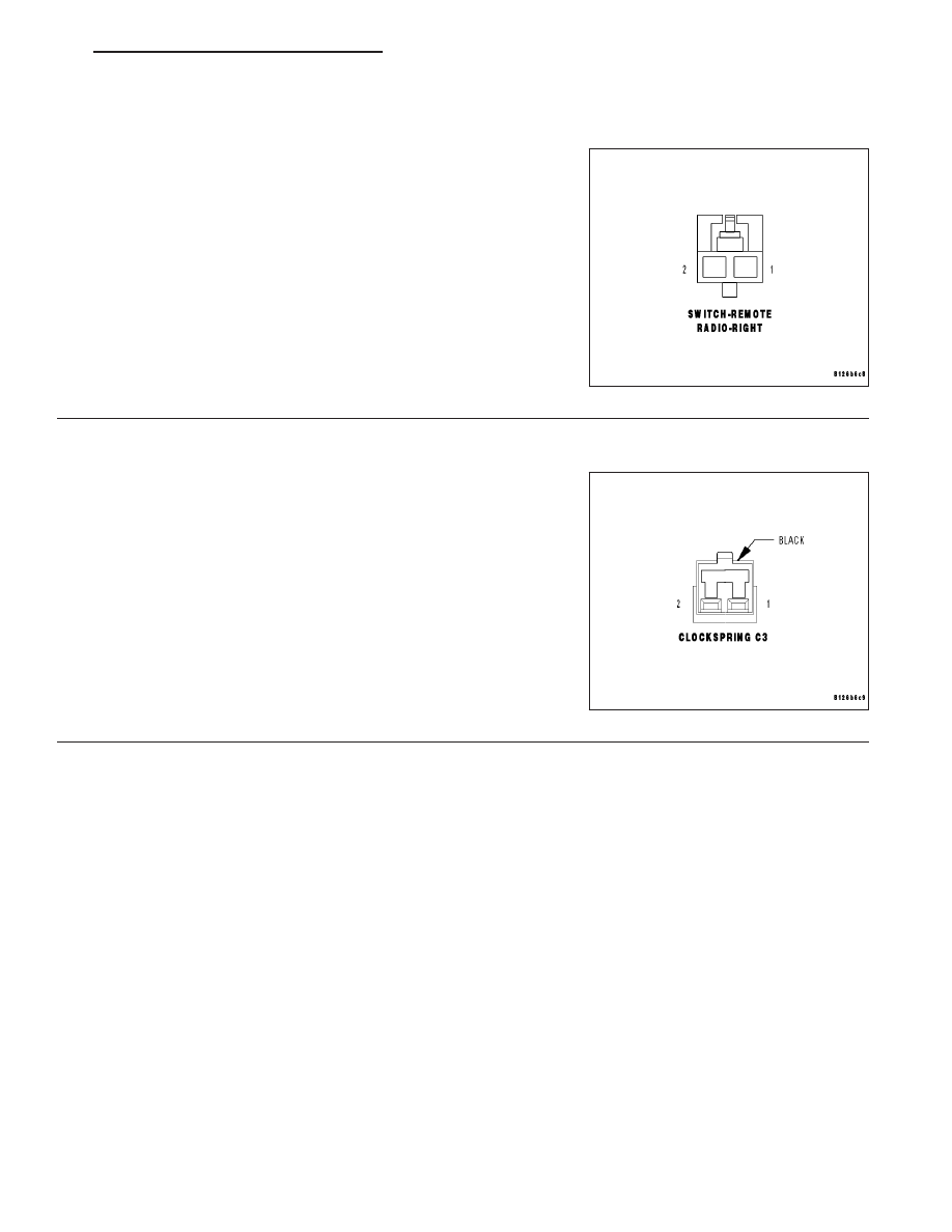
RIGHT REMOTE RADIO SWITCH
CLOCKSPRING
INSTRUMENT CLUSTER (CCN)
Diagnostic Test
1.
CHECK FOR ACTIVE DTC
With the scan tool, read the active DTC’s.
Cycle the ignition switch from off to on at least 5 times, leaving the ignition on for a minimum of 90 seconds per
cycle.
With the scan tool, read the active DTC’s.
Does the scan tool display this DTC as active?
Yes
>> Go To 2
No
>> If the DTC is stored, check for an intermittent condition. Visually inspect the related wiring harness con-
nectors. Look for broken, bent, pushed out, or corroded terminals.
2.
LEFT REMOTE RADIO SWITCH
Turn the ignition off.
Disconnect the Left Remote Radio Switch harness connector.
Turn the ignition on.
With the scan tool monitor the Remote Radio Control Switch voltage.
Is the voltage approximately 5.0 volts?
Yes
>> Replace the Left Remote Radio Switch in accordance with
the service information.
Perform BODY VERIFICATION TEST – VER 1.
No
>> Go To 3
8A - 50
AUDIO/VIDEO SYSTEMS - ELECTRICAL DIAGNOSIS
ND
B1428-REMOTE RADIO SWITCH INPUT CIRCUIT STUCK (CONTINUED)
3.
RIGHT REMOTE RADIO SWITCH
Turn the ignition off.
Disconnect the Right Remote Radio Switch harness connector.
Turn the ignition on.
With the scan tool monitor the Remote Radio Control Switch voltage.
Is the voltage approximately 5.0 volts?
Yes
>> Replace the Right Remote Radio Switch in accordance
with the service information.
Perform BODY VERIFICATION TEST – VER 1.
No
>> Go To 4
4.
CLOCKSPRING
Turn the ignition off.
Disconnect the Clockspring C1 harness connector.
Turn the ignition on.
With the scan tool monitor the Remote Radio Control Switch voltage.
Is the voltage approximately 5.0 volts?
Yes
>> Check the (X20) Radio Control MUX circuit for a short
between the clockspring and the remote radio switches. If
ok, replace the Clockspring in accordance with the service
information.
Perform BODY VERIFICATION TEST – VER 1.
No
>> Go To 5
ND
AUDIO/VIDEO SYSTEMS - ELECTRICAL DIAGNOSIS
8A - 51
B1428-REMOTE RADIO SWITCH INPUT CIRCUIT STUCK (CONTINUED)
5.
(X20) RADIO CONTROL MUX CIRCUIT SHORT TO GROUND
Turn the ignition off.
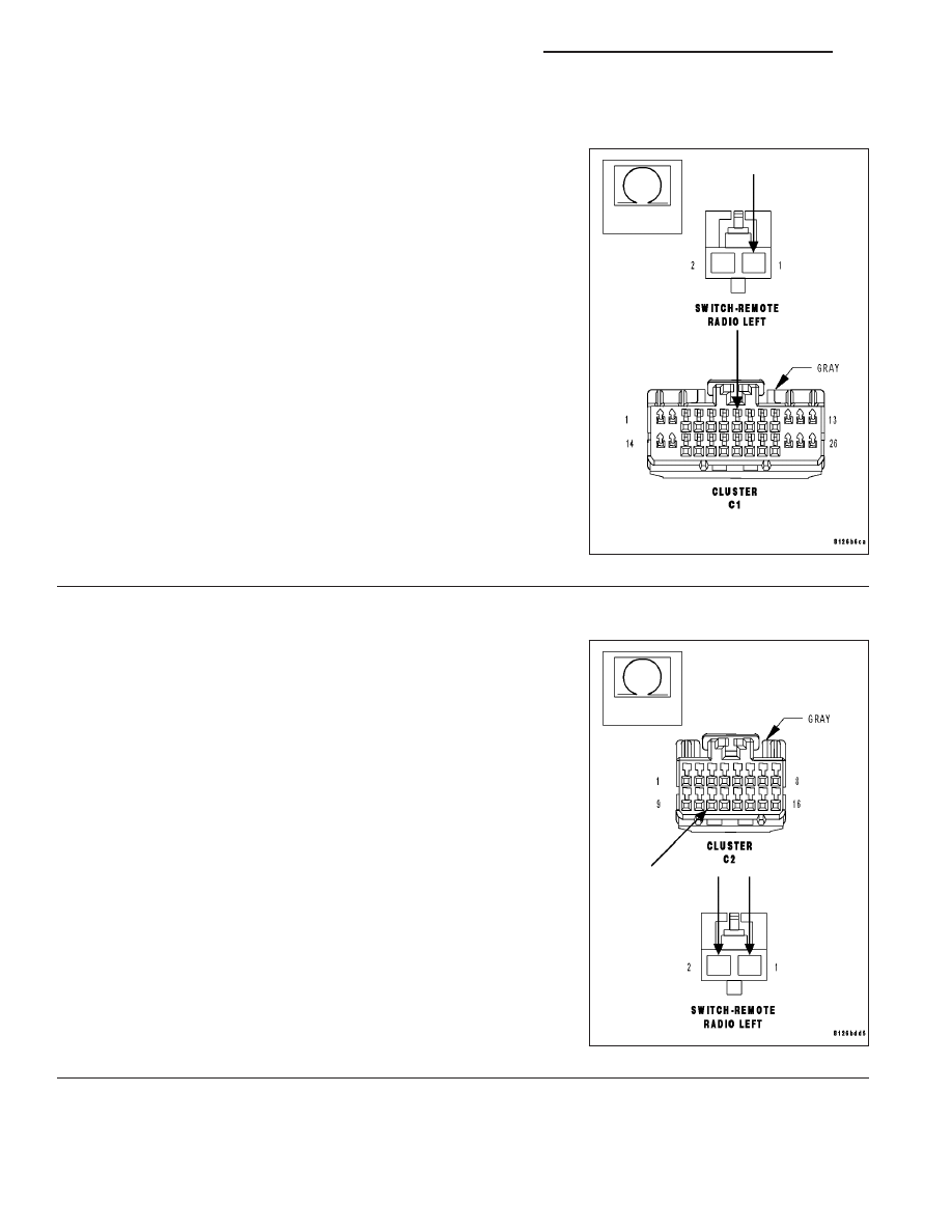
Disconnect the Instrument Cluster C1 harness connector.
Measure the resistance between ground and the (X20) Radio Control
MUX circuit.
Is the resistance below 100.0 ohms?
Yes
>> Repair the (X20) Radio Control MUX circuit for a short to
ground.
Perform BODY VERIFICATION TEST – VER 1.
No
>> Go To 6
6.
(X20) RADIO CONTROL MUX CIRCUIT SHORT TO (G902) SWITCH MUX RETURN CIRCUIT
Disconnect the Instrument Cluster C2 harness connector.
Measure the resistance between the (X20) Radio Control MUX circuit
and the (G902) Switch MUX Return circuit.
Is the resistance below 100.0 ohms?
Yes
>> Repair the (X20) Radio Control MUX circuit for a short to
the (G902) Switch MUX Return circuit.
Perform BODY VERIFICATION TEST – VER 1.
No
>> Inspect the wiring and connectors for damage or shorted
circuits. If ok, replace the Instrument Cluster (CCN) in
accordance with the service information.
Perform BODY VERIFICATION TEST – VER 1.
8A - 52
AUDIO/VIDEO SYSTEMS - ELECTRICAL DIAGNOSIS
ND
B1429-RADIO DISPLAY HIGH TEMPERATURE
For the Audio System circuit diagram (Refer to 8 - ELECTRICAL/AUDIO - SCHEMATICS AND DIAGRAMS).
For a complete wiring diagram Refer to Section 8W.
•
When Monitored:
•
Continuously with the ignition and Navigation Radio on.
•
Set Condition:
•
The code will set if the temperature inside the display exceeds 158°F
Possible Causes
HIGH TEMPERATURE FAILURE
Always perform the Pre-Diagnostic Troubleshooting procedure before proceeding.
Diagnostic Test
1.
VERIFY THAT DTC B1429—RADIO DISPLAY HIGH TEMPERATURE IS ACTIVE.
With the Scan Tool, erase the Audio DTC’s.
Start the engine and allow the engine to reach normal operating tem-
perature.
If the vehicle has been in the hot sunlight or extreme cold, move the
vehicle indoors and open the doors to allow the inside temperature to
stabilize.
The radio display should operate to 158°F.
With the Scan Tool, read the DTC’s.
Does the Scan Tool display, B1429— Radio Display High Tem-
perature?
Yes
>> Replace the Radio in accordance with the service informa-
tion.
Perform the BODY VERIFICATION TEST — VER 1.
No
>> Test Complete.
ND
AUDIO/VIDEO SYSTEMS - ELECTRICAL DIAGNOSIS
8A - 53
Нет комментариевНе стесняйтесь поделиться с нами вашим ценным мнением.
Текст