Dodge Dakota (ND). Manual — part 255
B2336,B2338–HORN CONTROL CIRCUIT LOW/OPEN – FCM (CONTINUED)
For the Horn System circuit diagram (Refer to 8 - ELECTRICAL/HORN SYSTEM - SCHEMATICS AND DIA-
GRAMS).
For a complete wiring diagram Refer to Section 8W.
•
When Monitored:
Continuously
•
Set Condition:
When the Front Control Module does not detect voltage on the Horn Relay Control circuit.
Possible Causes
HORN FUSE
B(+) OPEN
RELAY
POWER DISTRIBUTION CENTER
FRONT CONTROL MODULE
Diagnostic Test
1.
TEST FOR INTERMITTENT CONDITION
With the scan tool, record and erase DTC’s
Operate the Horn Switch several times.
Cycle the ignition from on to off 3 times and leave on.
With the scan tool, read DTC’s.
Does the scan tool display the same DTC?
Yes
>> Go To 2
No
>> The conditions that caused this code to set are not present at this time. Using the wiring diagram/sche-
matic as a guide, inspect the wiring and connectors.
Perform BODY VERIFICATION TEST - VER 1. (Refer to 8 - ELECTRICAL/HORN - DIAGNOSIS AND
TESTING)
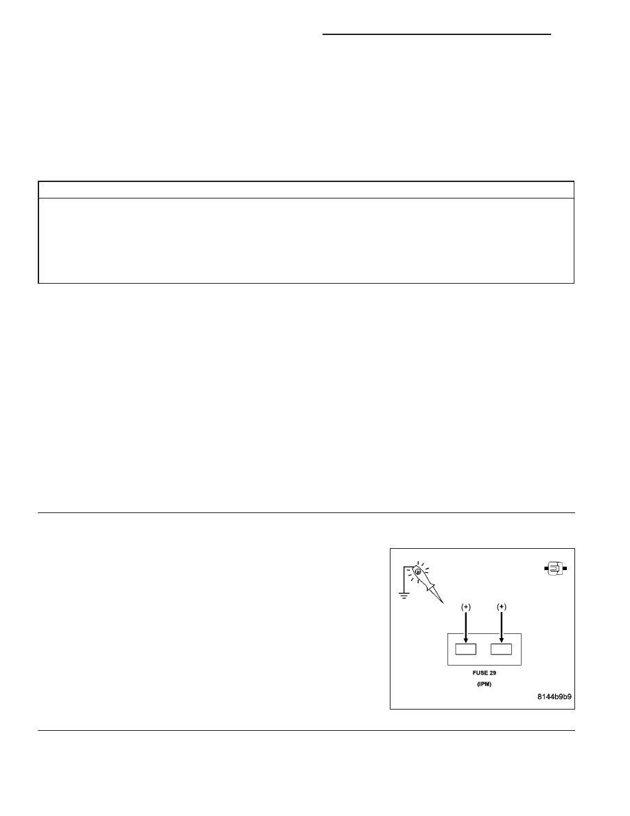
2.
HORN FUSE
Using a 12-volt test light connected to ground, check for voltage on
both sides of the Horn fuse.
Does the test light illuminate and was the fuse OK?
No
>> Replace the horn fuse if open and check for a short to
ground on the Horn Relay Output circuit or correct the
open B(+) circuit to the fuse.
Perform BODY VERIFICATION TEST - VER 1. (Refer to 8
- ELECTRICAL/HORN - DIAGNOSIS AND TESTING)
Yes
>> Go To 3
8H - 6
HORN SYSTEM - ELECTRICAL DIAGNOSTICS
ND
B2336,B2338–HORN CONTROL CIRCUIT LOW/OPEN – FCM (CONTINUED)
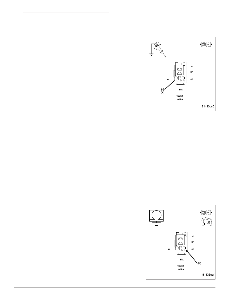
3.
OPEN FUSED B(+) TO RELAY
Remove the Horn Relay from the PDC.
Using a 12-volt test light connected to ground, check the Fused B(+)
circuit at the relay connector.
Does the test light illuminate?
No
>> Replace the Power Distribution Center in accordance with
the service information.
Perform BODY VERIFICATION TEST - VER 1. (Refer to 8
- ELECTRICAL/HORN - DIAGNOSIS AND TESTING)
Yes
>> Go To 4
4.
HORN RELAY
Install a known good relay in place of the Horn Relay.
With the scan tool erase DTC’s
Operate the Horn Switch several times.
Cycle the ignition from on to off 3 times and leave on.
With the scan tool, read DTC’s.
Does the scan tool display the same DTC?
No
>> Replace the original Horn Relay.
Perform BODY VERIFICATION TEST - VER 1. (Refer to 8 - ELECTRICAL/HORN - DIAGNOSIS AND
TESTING)
Yes
>> Go To 5
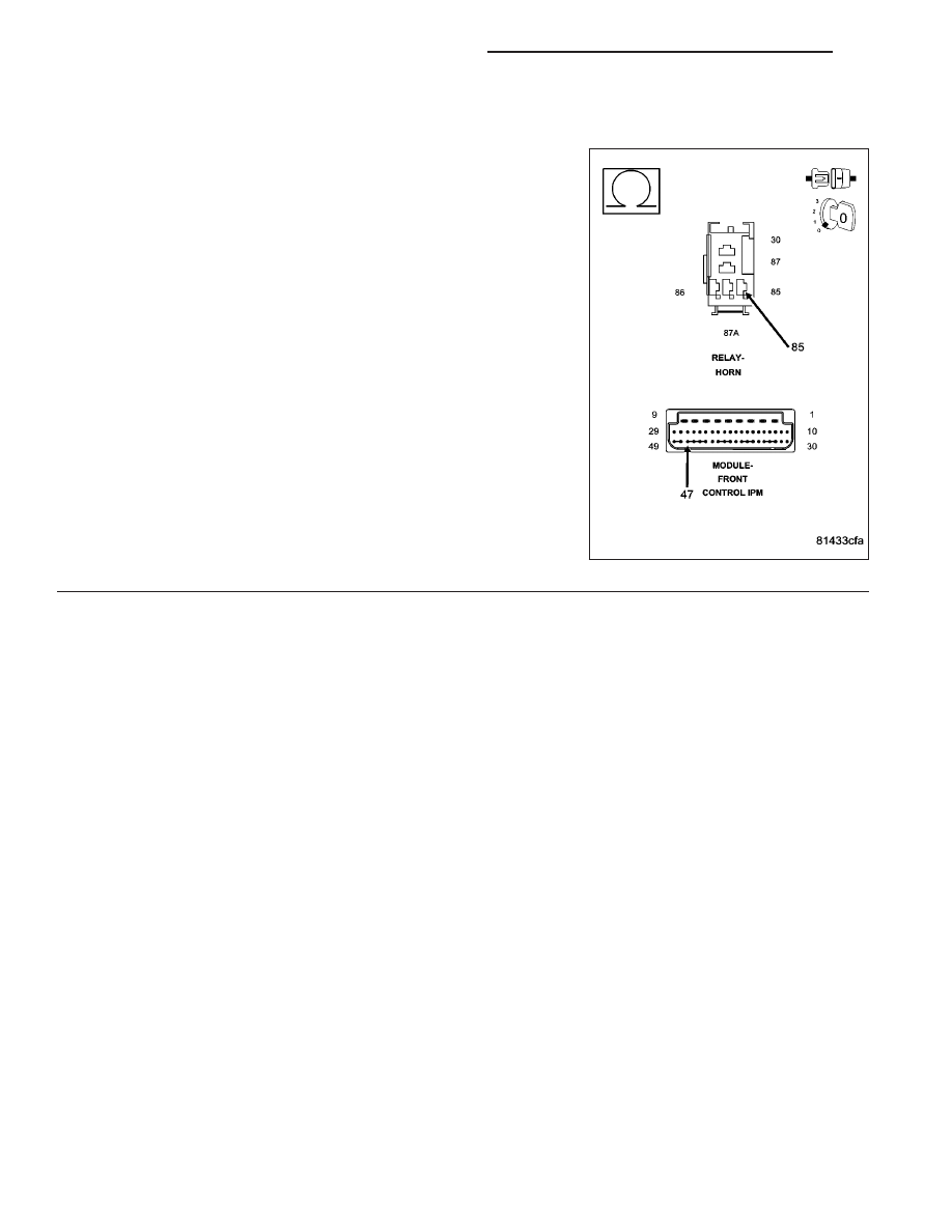
5.
(X4) HORN RELAY CONTROL SHORTED
Remove the Horn Relay.
Disconnect the Front Control Module from the PDC 49 – way connec-
tor.
Measure the resistance between ground and the (X4) Horn Relay
Control circuit at the relay.
Is the resistance below 1000.0 ohms?
Yes
>> Replace the Power Distribution Center in accordance with
the service information.
Perform BODY VERIFICATION TEST - VER 1. (Refer to 8
- ELECTRICAL/HORN - DIAGNOSIS AND TESTING)
No
>> Go To 6
ND
HORN SYSTEM - ELECTRICAL DIAGNOSTICS
8H - 7
B2336,B2338–HORN CONTROL CIRCUIT LOW/OPEN – FCM (CONTINUED)
6.
(X4)HORN RELAY CONTROL OPEN
Measure the resistance of the (X4)Horn Relay Control circuit from the
relay connector to FCM connector.
Is the resistance below 3.0 ohms?
Yes
>> Replace the Front Control Module in accordance with the
service information.
Perform BODY VERIFICATION TEST - VER 1. (Refer to 8
- ELECTRICAL/HORN - DIAGNOSIS AND TESTING)
No
>> Replace the Power Distribution Center in accordance with
the service information.
Perform BODY VERIFICATION TEST - VER 1. (Refer to 8
- ELECTRICAL/HORN - DIAGNOSIS AND TESTING)
8H - 8
HORN SYSTEM - ELECTRICAL DIAGNOSTICS
ND
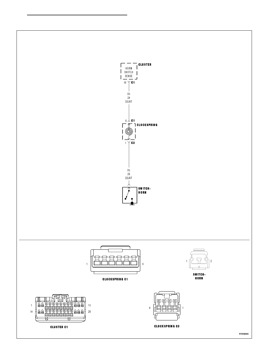
B2339–HORN SWITCH STUCK – CLUSTER
ND
HORN SYSTEM - ELECTRICAL DIAGNOSTICS
8H - 9
Нет комментариевНе стесняйтесь поделиться с нами вашим ценным мнением.
Текст