Dodge Dakota (ND). Manual — part 928
P0712-TRANSMISSION TEMPERATURE SENSOR LOW (CONTINUED)
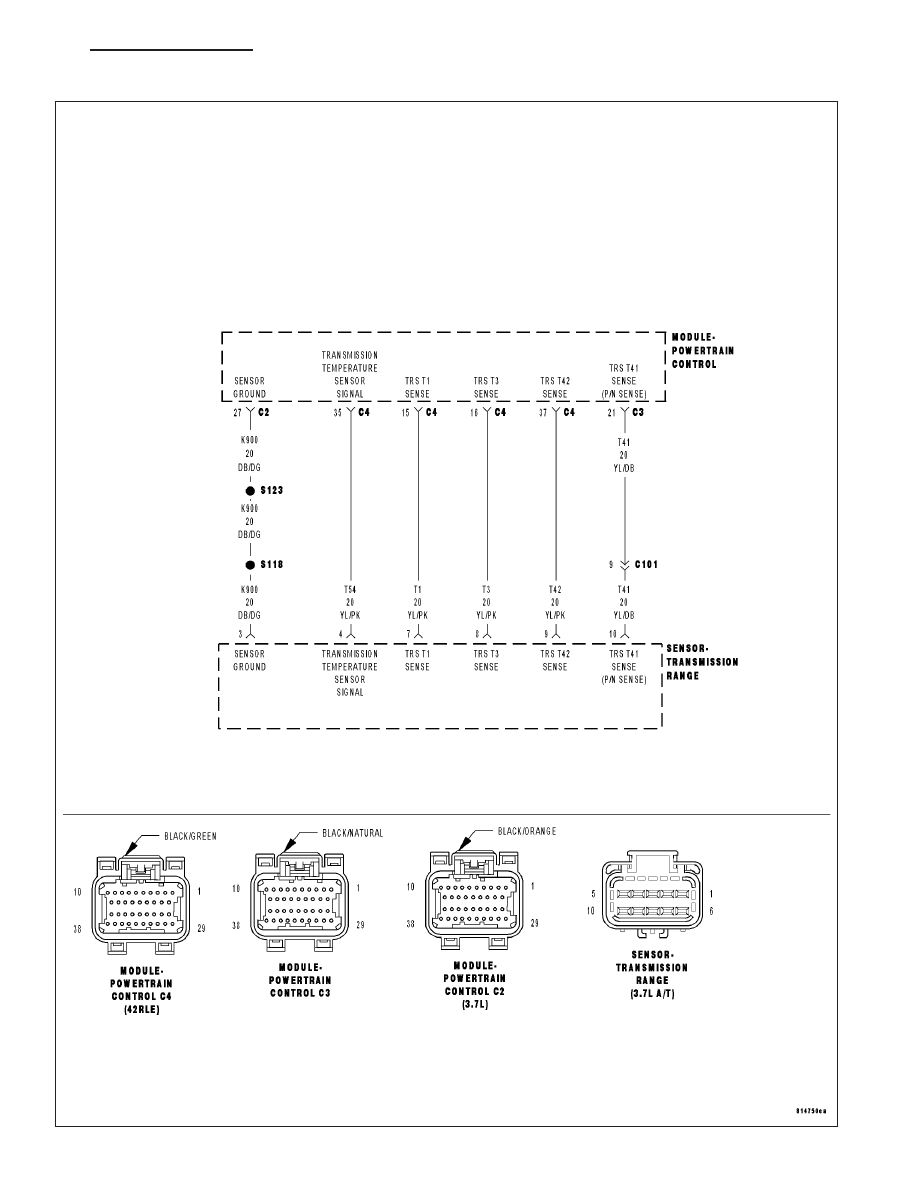
For the Transmission circuit diagram (Refer to 21 - TRANSMISSION/TRANSAXLE/AUTOMATIC - 42RLE - SCHE-
MATICS AND DIAGRAMS)
For a complete wiring diagram Refer to Section 8W.
•
When Monitored:
Continuously with the ignition on and engine running.
•
Set Condition:
The DTC will set when the monitored Temperature Sensor voltage drops below 0.078 volts for the period of
1.45 seconds. When the fault is set, calculated temperature is substituted for measured temperature, however
the fault code is stored only after three consecutive occurrences of the fault.
Possible Causes
RELATED DTCS PRESENT
(T54) TRANSMISSION TEMPERATURE SENSOR SIGNAL CIRCUIT SHORT TO GROUND
TRANSMISSION TEMPERATURE SENSOR
POWERTRAIN CONTROL MODULE
Always perform the Pre-Diagnostic Troubleshooting procedure before proceeding. (Refer to 21 - TRANSMIS-
SION/TRANSAXLE/AUTOMATIC - 42RLE - DIAGNOSIS AND TESTING).
Theory of Operation
The temperature sensor is used to sense the temperature of the transmission fluid. Transmission fluid temperature
can affect shift quality, torque converter operation and when or if some diagnostics are run. A failed temperature
sensor could affect the OBD diagnostics. If a problem occurs in the transmission temperature sensor circuit, trans-
mission temperature will be based on a calculated value.
Diagnostic Test
1.
DETERMINE IF RELATED DTCS ARE PRESENT
With the scan tool, check Transmission DTCs.
Are there any Speed Sensor DTCs present?
Yes
>> Refer to the Transmission category and perform the appropriate diagnostic procedure.
Perform 42RLE TRANSMISSION VERIFICATION TEST - VER 1.
No
>> Go To 2
2.
CHECK TO SEE IF DTC IS ACTIVE
With the scan tool, view DTCs.
Is the status Active for this DTC or is the STARTS SINCE SET counter 2 or less?
Yes
>> Go To 3
No
>> Go To 7
21 - 104
AUTOMATIC TRANSMISSION 42RLE - ELECTRICAL DIAGNOSTICS
ND
P0712-TRANSMISSION TEMPERATURE SENSOR LOW (CONTINUED)
3.
PCM AND WIRING
Turn the ignition off to the lock position.
Remove the Starter Relay.
CAUTION: Removal of the Starter Relay is to prevent a Transmission NO RESPONSE condition and to dis-
able the starter.
Install the Transmission Simulator, Miller tool #8333 and the Electronic Transmission Adapter kit 8333-1A.
NOTE: Check connectors - Clean/repair as necessary.
Ignition on, engine not running.
With the Transmission Simulator, turn the Input/Output switch to OFF.
With the scan tool, monitor the TRANS TEMP VOLTS while turning the Thermistor Voltage switch to all three posi-
tions on the Transmission Simulator.
Compare the scan tool readings with the numbers listed on the Transmission Simulator.
Do the readings on the Transmission Simulator match the scan tool readings ± 0.2 volts?
Yes
>> Go To 4
No
>> Go To 5
4.
TRANSMISSION TEMPERATURE SENSOR
If there are no possible causes remaining, view repair.
Repair
Replace Transmission Solenoid/TRS Assembly per the Service Information.
Perform 42RLE TRANSMISSION VERIFICATION TEST - VER 1.
5.
(T54) TRANSMISSION TEMPERATURE SENSOR SIGNAL
CIRCUIT SHORT TO GROUND
Turn the ignition off to the lock position.
Disconnect the PCM C4 harness connector.
Disconnect the TRS harness connector.
NOTE: Check connectors - Clean/repair as necessary.
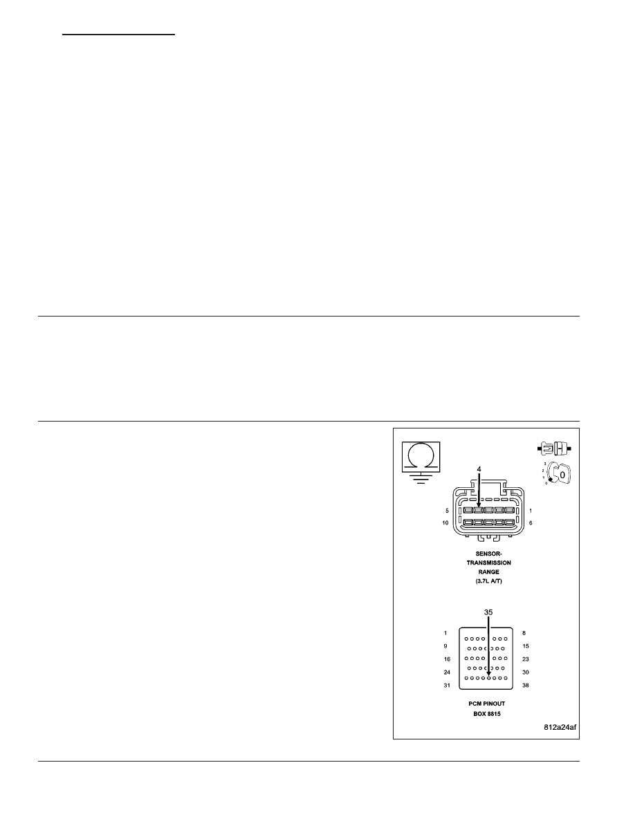
CAUTION: Do not probe the PCM harness connectors. Probing
the PCM harness connectors will damage the PCM terminals
resulting in poor terminal to pin connection. Install Miller Tool
#8815 to perform diagnosis.
Measure the resistance between ground and the (T54) Transmission
Temperature Sensor Signal circuit.
Is the resistance below 5.0 ohms?
Yes
>> Repair the (T54) Transmission Temperature Sensor Signal
circuit for a short to ground.
Perform 42RLE TRANSMISSION VERIFICATION TEST -
VER 1.
No
>> Go To 6
ND
AUTOMATIC TRANSMISSION 42RLE - ELECTRICAL DIAGNOSTICS
21 - 105
P0712-TRANSMISSION TEMPERATURE SENSOR LOW (CONTINUED)
6.
POWERTRAIN CONTROL MODULE
Using the schematics as a guide, inspect the wiring and connectors. Repair as necessary. Pay particular attention
to all power and ground circuits.
If there are no possible causes remaining, view repair.
Repair
Replace the Powertrain Control Module per the Service Information. With the scan tool perform QUICK
LEARN
Perform 42RLE TRANSMISSION VERIFICATION TEST - VER 1.
7.
INTERMITTENT WIRING AND CONNECTORS
The conditions necessary to set this DTC are not present at this time.
Using the schematics as a guide, inspect the wiring and connectors specific to this circuit.
Wiggle the wires while checking for shorted and open circuits.
With the scan tool, check the EATX DTC EVENT DATA to help identify the conditions in which the DTC was set.
Were there any problems found?
Yes
>> Repair as necessary.
Perform 42RLE TRANSMISSION VERIFICATION TEST - VER 1.
No
>> Test Complete.
21 - 106
AUTOMATIC TRANSMISSION 42RLE - ELECTRICAL DIAGNOSTICS
ND
P0713-TRANSMISSION TEMPERATURE SENSOR HIGH
ND
AUTOMATIC TRANSMISSION 42RLE - ELECTRICAL DIAGNOSTICS
21 - 107
Нет комментариевНе стесняйтесь поделиться с нами вашим ценным мнением.
Текст