Dodge Dakota (ND). Manual — part 187
B210E-BATTERY VOLTAGE HIGH
For a complete wiring diagram Refer to Section 8W.
•
When Monitored:
With the ignition on.
•
Set Condition:
Battery voltage greater than 16 volts for more than 15 seconds.
Possible Causes
(K20) GENERATOR FIELD CONTROL CIRCUIT SHORTED TO BATTERY VOLTAGE
GENERATOR
PCM
Diagnostic Test
1.
CHECK FOR ANY POWERTRAIN CONTROL MODULES DTCS
NOTE: Make sure the Battery is in good condition. Using the Midtronics Battery Tester, test the Battery
before continuing.
NOTE: Inspect the vehicle for after market accessories that may exceed the Generator System output.
NOTE: Make sure the generator drive belt is in good operating condition.
NOTE: Inspect the fuses in the IPM. If an open fuse is found, use the wire diagram/schematic as a guide,
inspect the wiring and connectors for damage.
Turn the ignition on.
With the scan tool, read active PCM DTC’s.
Does the scan tool display any active PCM DTC’s?
Yes
>> (Refer to 9 - ENGINE - DIAGNOSIS AND TESTING) for the diagnostic test procedure.
No
>> Check the above conditions that can cause a high voltage condition. Repair as necessary.
Perform BODY VERIFICATION TEST - VER 1. (Refer to BODY VERIFICATION TEST - VER 1).
8E - 4
ELECTRONIC CONTROL MODULES - ELECTRICAL DIAGNOSTICS
ND
B2112-5 VOLT SUPPLY CIRCUIT LOW
ND
ELECTRONIC CONTROL MODULES - ELECTRICAL DIAGNOSTICS
8E - 5

B2112-5 VOLT SUPPLY CIRCUIT LOW (CONTINUED)
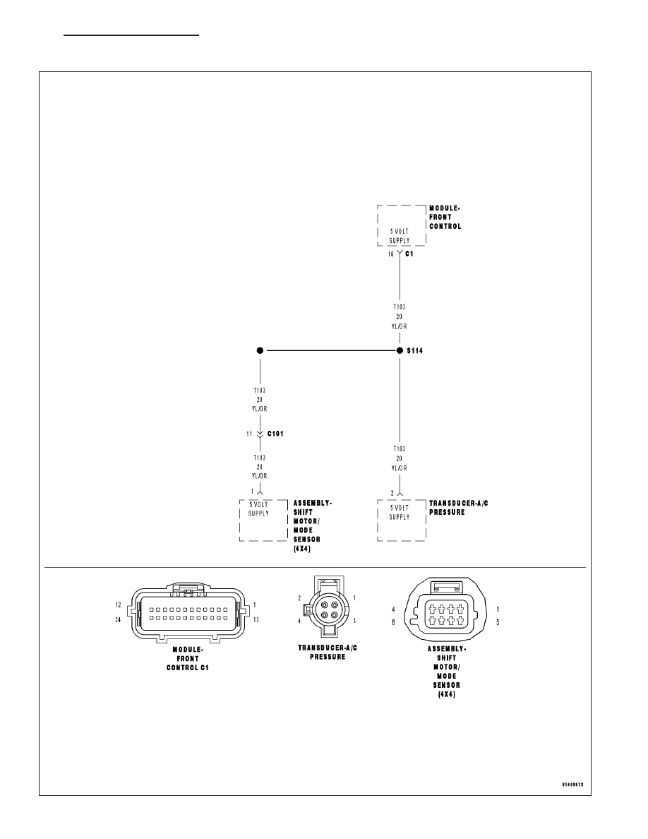
For a complete wiring diagram Refer to Section 8W.
•
When Monitored:
With the ignition on.
•
Set Condition:
The Front Control Module detects the (T103) 5 volt supply circuit voltage below 0.3 volts.
Possible Causes
(T103) 5 VOLT SUPPLY CIRCUIT SHORTED TO GROUND
A/C PRESSURE TRANSDUCER
SHIFT MOTOR/MODE SENSOR ASSEMBLY
FRONT CONTROL MODULE
Diagnostic Test
1.
CHECK FOR ACTIVE DTC
With the scan tool, read the active DTC’s.
Cycle the ignition switch from off to on, leaving the ignition on for a minimum of 90 seconds.
With the scan tool, read the active DTC’s.
Does the scan tool display this DTC as active?
Yes
>> Go To 2
No
>> If the DTC is stored, check for an intermittent condition. Visually inspect the related wiring harness con-
nectors. Look for broken, bent, pushed out, or corroded terminals.
2.
A/C PRESSURE TRANSDUCER
Turn the ignition off.
Disconnect the A/C Pressure Transducer harness connector.
Cycle the ignition switch from off to on, leaving the ignition on for a minimum of 90 seconds.
With the scan tool, read the active DTC’s.
Does the scan tool display this DTC as active?
Yes
>> Go To 3
No
>> Replace the A/C Pressure Transducer in accordance with the service information.
Perform BODY VERIFICATION TEST - VER 1. (Refer to BODY VERIFICATION TEST - VER 1).
3.
SHIFT MOTOR/MODE SENSOR ASSEMBLY
Turn the ignition off.
Disconnect the Shift Motor/Mode Sensor Assembly harness connector.
Cycle the ignition switch from off to on, leaving the ignition on for a minimum of 90 seconds.
With the scan tool, read the active DTC’s.
Does the scan tool display this DTC as active?
Yes
>> Go To 4
No
>> Replace the Shift Motor/Mode Sensor Assembly in accordance with the service information.
Perform BODY VERIFICATION TEST - VER 1. (Refer to BODY VERIFICATION TEST - VER 1).
8E - 6
ELECTRONIC CONTROL MODULES - ELECTRICAL DIAGNOSTICS
ND
B2112-5 VOLT SUPPLY CIRCUIT LOW (CONTINUED)
4.
(T103) 5 VOLT SUPPLY CIRCUIT SHORTED TO GROUND
Turn the ignition off.
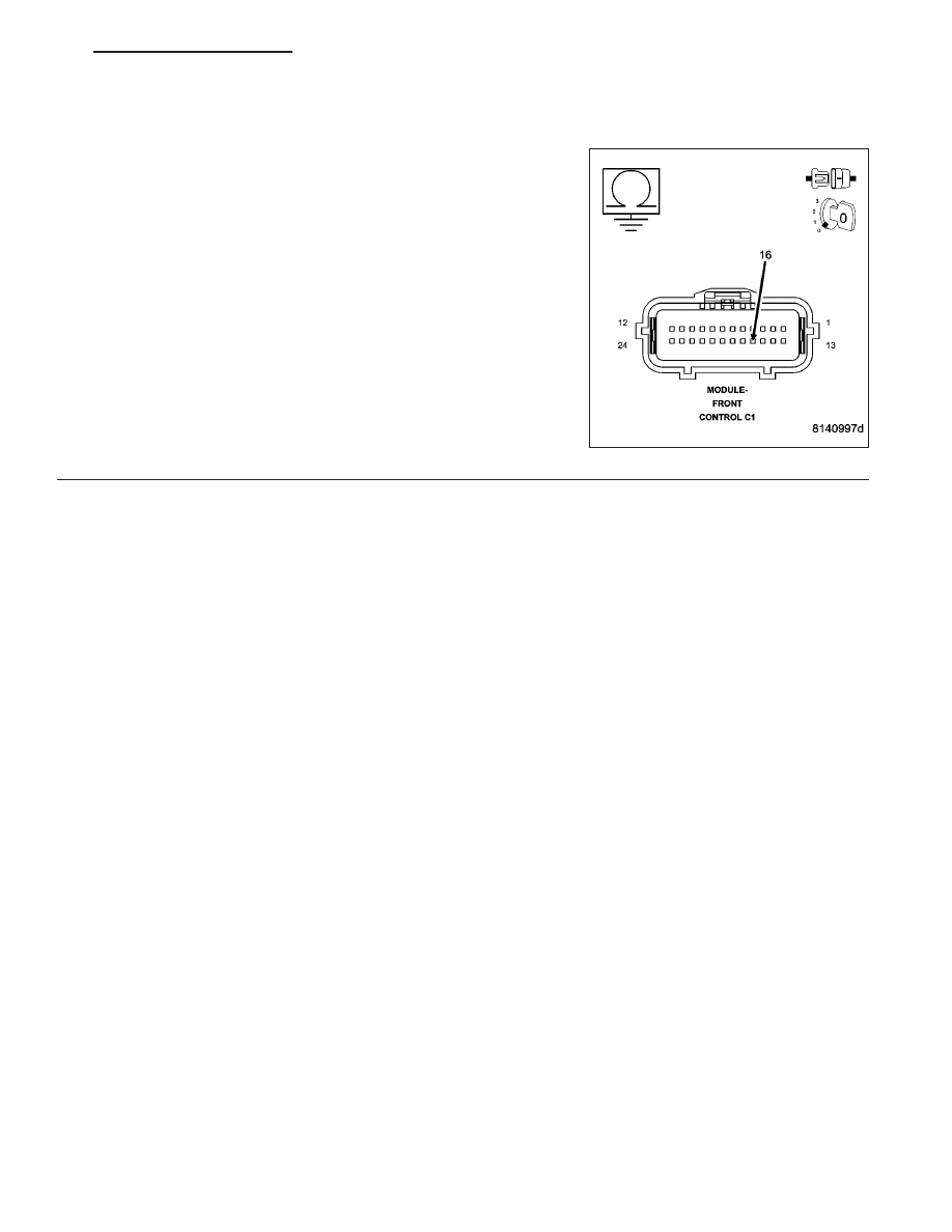
Disconnect the FCM C1 harness connector.
Measure the resistance between ground and the (T103) 5 Volt Supply
circuit.
Is the resistance below 1000.0 ohms?
Yes
>> Repair the (T103) 5 Volt Supply circuit for a short to
ground.
Perform BODY VERIFICATION TEST - VER 1. (Refer to
BODY VERIFICATION TEST - VER 1).
No
>> Inspect the wiring and connectors for damage or shorted
circuits. If ok, replace and program the Front Control Mod-
ule in accordance with the service information.
Perform BODY VERIFICATION TEST - VER 1. (Refer to
BODY VERIFICATION TEST - VER 1).
ND
ELECTRONIC CONTROL MODULES - ELECTRICAL DIAGNOSTICS
8E - 7
Нет комментариевНе стесняйтесь поделиться с нами вашим ценным мнением.
Текст