Dodge Dakota (ND). Manual — part 651
P0132-O2 SENSOR 1/1 CIRCUIT HIGH (CONTINUED)
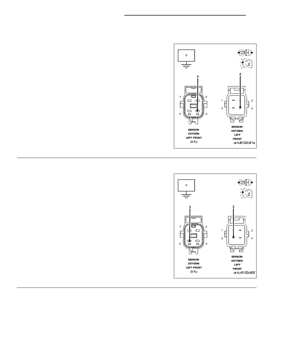
2.
(K41) O2 1/1 SIGNAL CIRCUIT SHORTED TO BATTERY VOLTAGE
Start the engine and allow the engine to idle.
Disconnect the 1/1 O2 Sensor harness connector.
Measure the voltage on the (K41) O2 Sensor 1/1 Signal circuit in the
1/1 O2 Sensor harness connector.
NOTE: Measure the voltage in reference to ground, not the (K902)
O2 Return Upstream circuit.
Is the voltage above 0 volts?
Yes
>> Repair the short to battery voltage in the (K41) O2 Sensor
1/1 Signal circuit.
Perform POWERTRAIN VERIFICATION TEST. (Refer to 9
- ENGINE - STANDARD PROCEDURE)
No
>> Go To 3
3.
(K902) O2 RETURN UPSTREAM CIRCUIT SHORTED TO BATTERY VOLTAGE
Turn the ignition off.
Disconnect the C1 PCM harness connector.
Ignition on, engine not running.
Measure the voltage on the (K902) O2 Return Upstream circuit in the
1/1 O2 Sensor harness connector.
Is there any voltage present?
Yes
>> Repair the short to battery voltage in the (K902) O2
Return Upstream circuit.
Perform POWERTRAIN VERIFICATION TEST. (Refer to 9
- ENGINE - STANDARD PROCEDURE) S
No
>> Go To 4
9 - 142
ENGINE ELECTRICAL DIAGNOSTICS
ND
P0132-O2 SENSOR 1/1 CIRCUIT HIGH (CONTINUED)
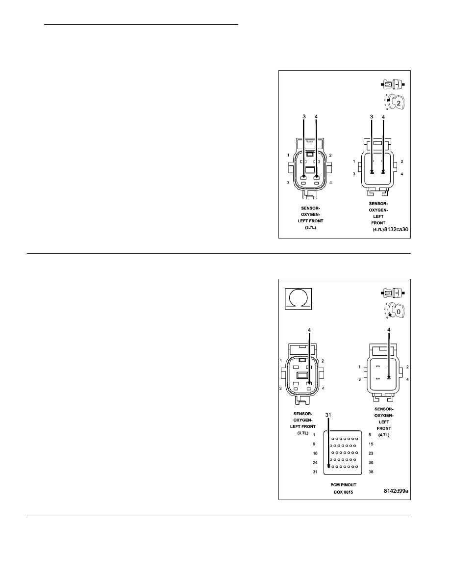
4.
1/1 O2 SENSOR
Turn the ignition off.
Connect the C1 PCM harness connector.
Connect a jumper wire between the (K41) O2 1/1 Signal circuit and
the (K902) O2 Return Upstream circuit in the O2 Sensor harness con-
nector.
Ignition on, engine not running.
With a scan tool, monitor the 1/1 O2 Sensor voltage.
Is the voltage between 2.3 and 2.7 volts with the jumper wire
installed?
Yes
>> Replace the O2 Sensor.
Perform POWERTRAIN VERIFICATION TEST. (Refer to 9
- ENGINE - STANDARD PROCEDURE)
No
>> Go To 5
NOTE: Remove the jumper wire before continuing.
5.
(K41) O2 1/1 SIGNAL CIRCUIT OPEN
Turn the ignition off.
Disconnect the C1 and C2 PCM harness connectors.
CAUTION: Do not probe the PCM harness connectors. Probing
the PCM harness connectors will damage the PCM terminals
resulting in poor terminal to pin connection. Install Miller Special
Tool #8815 to perform diagnosis.
Measure the resistance of the (K41) O2 1/1 Signal circuit from the 1/1
O2 Sensor harness connector to the appropriate terminal of special
tool #8815.
Is the resistance below 5.0 ohms?
Yes
>> Go To 6
No
>> Repair the open in the (K41) O2 1/1 Signal circuit.
Perform POWERTRAIN VERIFICATION TEST. (Refer to 9
- ENGINE - STANDARD PROCEDURE)
ND
ENGINE ELECTRICAL DIAGNOSTICS
9 - 143
P0132-O2 SENSOR 1/1 CIRCUIT HIGH (CONTINUED)
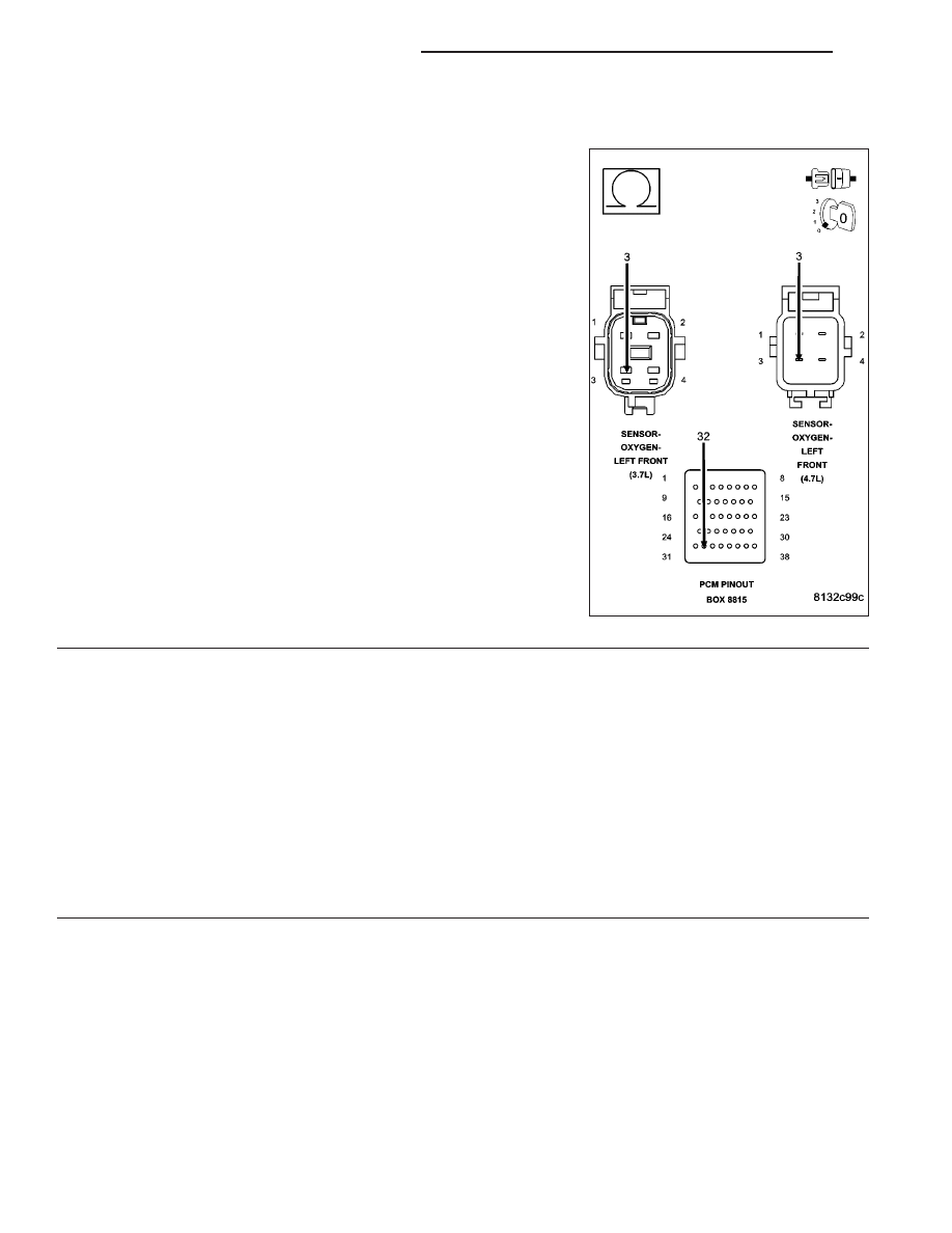
6.
(K902) O2 RETURN UPSTREAM CIRCUIT OPEN
Measure the resistance of the (K902) O2 Return Upstream circuit from
the O2 Sensor harness connector to the appropriate terminal of spe-
cial tool #8815.
Is the resistance below 5.0 ohms?
Yes
>> Go To 7
No
>> Repair the open in the (K902) O2 Return Upstream circuit.
Perform POWERTRAIN VERIFICATION TEST. (Refer to 9
- ENGINE - STANDARD PROCEDURE)
7.
PCM
NOTE: Before continuing, check the PCM harness connector terminals for corrosion, damage, or terminal
push out. Repair as necessary.
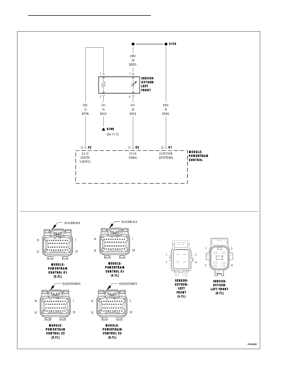
Using the schematics as a guide, inspect the wire harness and connectors. Pay particular attention to all Power and
Ground circuits.
Were there any problems found?
Yes
>> Repair as necessary.
Perform POWERTRAIN VERIFICATION TEST. (Refer to 9 - ENGINE - STANDARD PROCEDURE)
No
>> Replace and program the Powertrain Control Module per Service Information.
Perform POWERTRAIN VERIFICATION TEST. (Refer to 9 - ENGINE - STANDARD PROCEDURE)
9 - 144
ENGINE ELECTRICAL DIAGNOSTICS
ND
P0133-O2 SENSOR 1/1 SLOW RESPONSE
ND
ENGINE ELECTRICAL DIAGNOSTICS
9 - 145
Нет комментариевНе стесняйтесь поделиться с нами вашим ценным мнением.
Текст