Dodge Dakota (ND). Manual — part 950
P0888-TRANSMISSION RELAY ALWAYS OFF
21 - 192
AUTOMATIC TRANSMISSION 42RLE - ELECTRICAL DIAGNOSTICS
ND

P0888-TRANSMISSION RELAY ALWAYS OFF (CONTINUED)
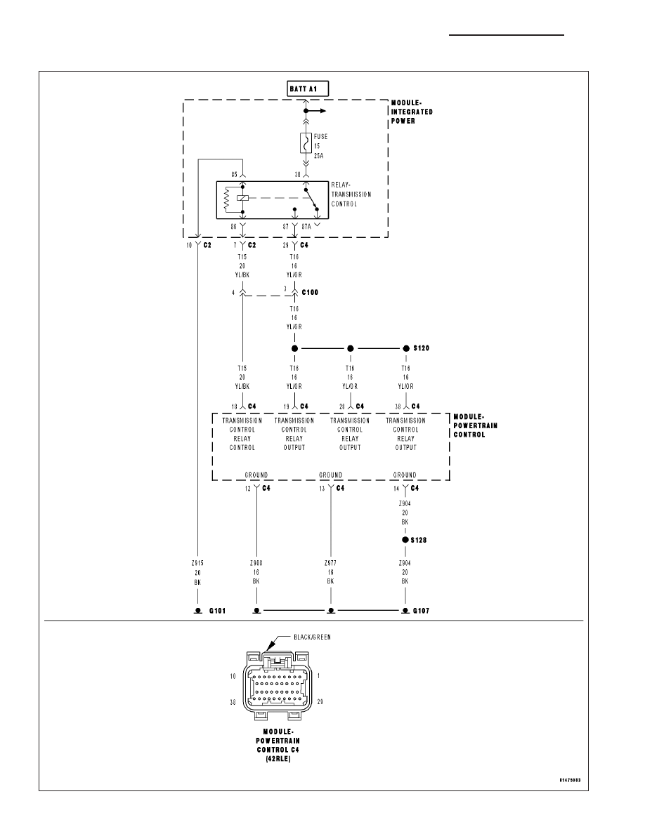
For the Transmission circuit diagram (Refer to 21 - TRANSMISSION/TRANSAXLE/AUTOMATIC - 42RLE - SCHE-
MATICS AND DIAGRAMS)
For a complete wiring diagram Refer to Section 8W.
•
When Monitored:
Continuously
•
Set Condition:
This DTC is set when the Transmission Control Relay output circuit voltage at the Powertrain Control Module
is less than 3 volts when the PCM is energizing the relay. Note: Due to the integration of the Powertrain and
Transmission Control Modules, the transmission part of the PCM has its own specific power and ground cir-
cuits.
Possible Causes
(A104) FUSED B+ CIRCUIT OPEN
(T16) TRANSMISSION CONTROL RELAY OUTPUT CIRCUIT OPEN
(T15) TRANSMISSION CONTROL RELAY CONTROL CIRCUIT OPEN
(Z915) TRANSMISSION CONTROL RELAY GROUND CIRCUIT OPEN
(T15) TRANSMISSION CONTROL RELAY CONTROL CIRCUIT SHORT TO GROUND
(T16) TRANSMISSION CONTROL RELAY OUTPUT CIRCUIT SHORT TO GROUND
TRANSMISSION CONTROL RELAY
TRANSMISSION SOLENOID/PRESSURE SWITCH ASSEMBLY
POWERTRAIN CONTROL MODULE
Always perform the Pre-Diagnostic Troubleshooting procedure before proceeding. (Refer to 21 - TRANSMIS-
SION/TRANSAXLE/AUTOMATIC - 42RLE - DIAGNOSIS AND TESTING).
Theory of Operation
The transmission control relay is used to supply power to the solenoid pack when the transmission is in normal
operating mode. When the relay is off, no power is supplied to the solenoid pack and the transmission is in Limp-in
mode. The relay output is fed back to the PCM. It is referred to as the Trans Relay Output circuit or switched
battery. After a controller reset (ignition key turned to the run position or after cranking engine), the controller ener-
gizes the relay. Prior to this, the PCM verifies that the contacts are open by checking for no voltage at the trans-
mission control relay outputs (switched battery) terminals. After the relay is energized, the PCM monitors the
terminals to verify that the voltage is greater than 3 volts. The MIL illuminates and the transmission will be placed
in Limp-in.
Diagnostic Test
1.
CHECK TO SEE IF DTC P0888 IS CURRENT
With the scan tool, view DTCs.
Is the status Active for this DTC or is the STARTS SINCE SET counter equal to 0?
Yes
>> Go To 2
No
>> Go To 12
ND
AUTOMATIC TRANSMISSION 42RLE - ELECTRICAL DIAGNOSTICS
21 - 193

P0888-TRANSMISSION RELAY ALWAYS OFF (CONTINUED)
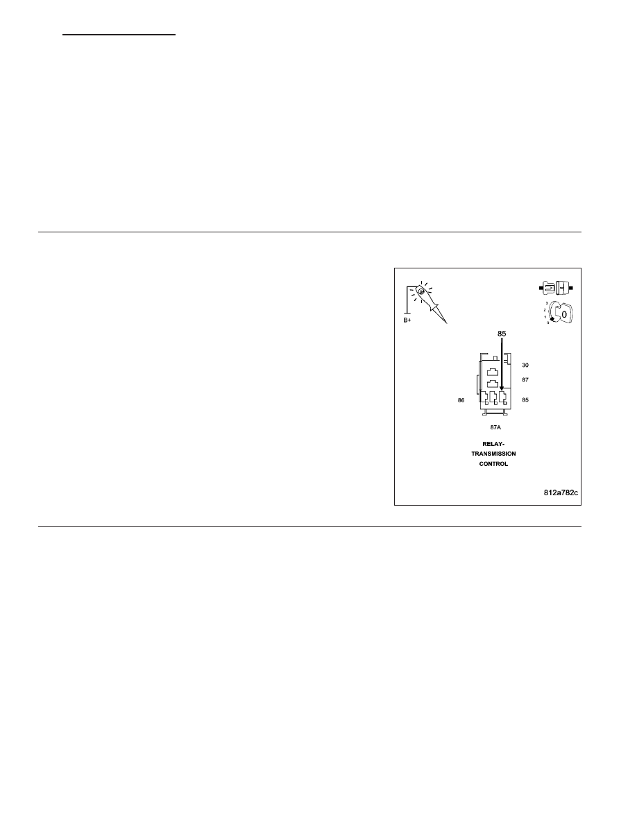
2.
CHECK THE (A104) FUSED B+ CIRCUIT
Turn the ignition off to the lock position.
Remove the Transmission Control Relay.
NOTE: Check connectors - Clean/repair as necessary.
Using a 12-volt test light connected to ground, check the (A104) Fused
B+ circuit in the Transmission Control Relay connector.
NOTE: The test light must illuminate brightly. Compare the bright-
ness to that of a direct connection to the battery.
Does the test light illuminate brightly?
Yes
>> Go To 3
No
>> Go To 9
3.
(T16) TRANSMISSION CONTROL RELAY OUTPUT CIRCUIT OPEN
Connect a jumper wire between the (A104) Fused B+ circuit and the
(T16) Transmission Control Relay Output circuits at the Transmission
Control Relay connector.
Ignition on, engine not running.
With the scan tool, read the Transmission Switched Battery voltage.
Is the Switched Battery voltage equal to battery voltage?
Yes
>> Go To 4
No
>> Repair the (T16) Transmission Control Relay Output cir-
cuits for an open or high resistance. Note: There are mul-
tiple Transmission Control Relay Output circuits.
Perform 42RLE TRANSMISSION VERIFICATION TEST -
VER 1.
21 - 194
AUTOMATIC TRANSMISSION 42RLE - ELECTRICAL DIAGNOSTICS
ND
P0888-TRANSMISSION RELAY ALWAYS OFF (CONTINUED)
4.
TRANSMISSION CONTROL RELAY
Turn the ignition off to the lock position.
Install a substitute Relay in place of the Transmission Control Relay.
Ignition on, engine not running.
With the scan tool, read the Transmission Switched Battery voltage.
Is the Switched Battery voltage equal to battery voltage?
Yes
>> Replace the Transmission Control Relay.
Perform 42RLE TRANSMISSION VERIFICATION TEST - VER 1.
No
>> Go To 5
5.
(Z915) TRANSMISSION CONTROL RELAY GROUND CIRCUIT OPEN
Using a 12-volt test light connected to 12-volts, check the (Z915)
Transmission Control Relay Ground circuit.
NOTE: The test light must illuminate brightly. Compare the bright-
ness to that of a direct connection to the battery.
Does the test light illuminate brightly?
Yes
>> Go To 6
No
>> Repair the (Z915) Transmission Control Relay Ground cir-
cuit for an open.
Perform 42RLE TRANSMISSION VERIFICATION TEST -
VER 1.
ND
AUTOMATIC TRANSMISSION 42RLE - ELECTRICAL DIAGNOSTICS
21 - 195
Нет комментариевНе стесняйтесь поделиться с нами вашим ценным мнением.
Текст