Dodge Dakota (ND). Manual — part 763
P0685-AUTO SHUTDOWN RELAY CONTROL CIRCUIT (CONTINUED)
6.
PCM
NOTE: Before continuing, check the PCM harness connector terminals for corrosion, damage, or terminal
push out. Repair as necessary.
Using the schematics as a guide, inspect the wire harness and connectors. Pay particular attention to all Power and
Ground circuits.
Were there any problems found?
Yes
>> Repair as necessary.
Perform POWERTRAIN VERIFICATION TEST. (Refer to 9 - ENGINE - STANDARD PROCEDURE)
No
>> Replace and program the Powertrain Control Module per Service Information.
Perform POWERTRAIN VERIFICATION TEST. (Refer to 9 - ENGINE - STANDARD PROCEDURE)
9 - 590
ENGINE ELECTRICAL DIAGNOSTICS
ND

P0688-AUTO SHUTDOWN RELAY SENSE CIRCUIT LOW
ND
ENGINE ELECTRICAL DIAGNOSTICS
9 - 591
P0688-AUTO SHUTDOWN RELAY SENSE CIRCUIT LOW (CONTINUED)
For the Engine circuit diagram (Refer to 9 - ENGINE - SCHEMATICS AND DIAGRAMS).
For a complete wiring diagram Refer to Section 8W.
•
When Monitored:
With ignition key on. Battery voltage greater than 10 volts.
•
Set Condition:
No voltage sensed at the PCM when the ASD relay is energized. One Trip Fault. Three good trips to turn off
the MIL.
Possible Causes
INTERNAL FUSED B+ CIRCUITS
(A955) ASD RELAY OUTPUT CIRCUIT OPEN
ASD RELAY
PCM
Always perform the Pre-Diagnostic Troubleshooting procedure before proceeding. (Refer to 9 - ENGINE -
DIAGNOSIS AND TESTING).
Diagnostic Test
1.
VERIFY ASD DTC
NOTE: Diagnose P0685 - Auto Shutdown Relay Control Circuit first if it set along with this DTC.
With a scan tool, erase the DTC.
Attempt to start the engine. If the engine will not start, crank the engine for at least 15 seconds. It may be neces-
sary to repeat several times.
Does the DTC reset?
Yes
>> Go To 2
No
>> Refer to the INTERMITTENT CONDITION Diagnostic Procedure.
Perform POWERTRAIN VERIFICATION TEST. (Refer to 9 - ENGINE - STANDARD PROCEDURE)
2.
ENGINE OPERATION
Attempt to start the engine.
Does the engine start?
Yes
>> Go To 3
No
>> Go To 4
9 - 592
ENGINE ELECTRICAL DIAGNOSTICS
ND
P0688-AUTO SHUTDOWN RELAY SENSE CIRCUIT LOW (CONTINUED)
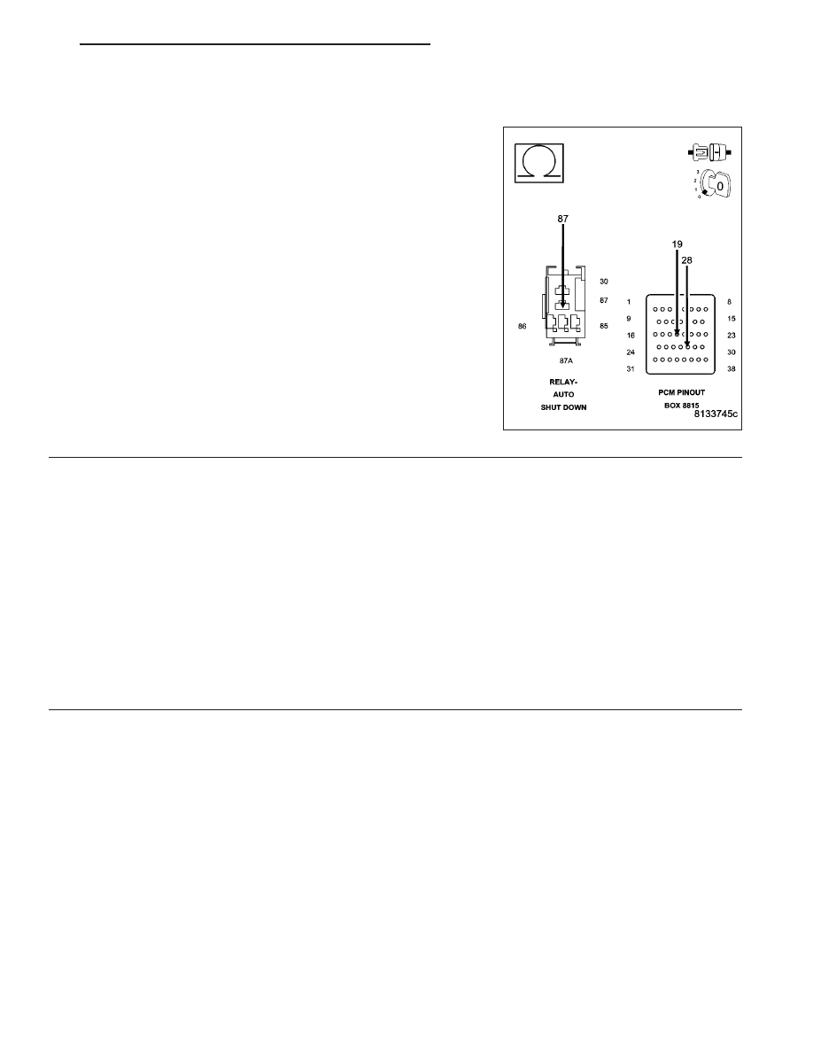
3.
(A955) ASD RELAY OUTPUT CIRCUIT OPEN
Turn the ignition off.
Remove the ASD Relay.
Disconnect the C3 PCM harness connector.
CAUTION: Do not probe the PCM harness connectors. Probing
the PCM harness connectors will damage the PCM terminals
resulting in poor terminal to pin connection. Install Miller Special
Tool #8815 to perform diagnosis.
Measure the resistance of the (A955) ASD Relay Output circuit from
the Relay connection to the appropriate terminals of special tool
#8815.
Is the resistance below 5.0 ohms?
Yes
>> Go To 7
No
>> Repair the open in the (A955) ASD Relay Output circuit.
Perform POWERTRAIN VERIFICATION TEST. (Refer to 9
- ENGINE - STANDARD PROCEDURE)
4.
ASD RELAY
Turn the ignition off.
Install a substitute relay in place of the ASD Relay.
Ignition on, engine not running.
With a scan tool, erase DTCs.
Attempt to start the engine.
With a scan tool, read DTCs.
Does the DTC reset?
Yes
>> Go To 5
No
>> Replace the ASD Relay.
Perform POWERTRAIN VERIFICATION TEST. (Refer to 9 - ENGINE - STANDARD PROCEDURE)
ND
ENGINE ELECTRICAL DIAGNOSTICS
9 - 593
Нет комментариевНе стесняйтесь поделиться с нами вашим ценным мнением.
Текст