Dodge Dakota (ND). Manual — part 521
B1437-VOICE RECOGNITION/PHONE SWITCH INPUT CIRCUIT HIGH (CONTINUED)
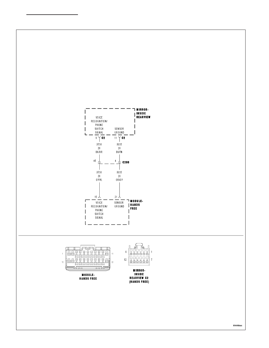
For a complete wiring diagram Refer to Section 8W.
•
When Monitored:
With the ignition on.
•
Set Condition:
The Hands Free Module detects voltage above 4.7 volts on the (X730) Voice Recognition/Phone Switch Signal
circuit.
Possible Causes
(X730) VOICE RECOGNITION/PHONE SWITCH SIGNAL CIRCUIT SHORT TO VOLTAGE
(X730) VOICE RECOGNITION/PHONE SWITCH SIGNAL CIRCUIT OPEN
(X835) SENSOR GROUND CIRCUIT OPEN
INSIDE REARVIEW MIRROR
HANDS FREE MODULE
Diagnostic Test
1.
CHECK FOR ACTIVE DTCS
With the scan tool, read the active DTC’s.
Cycle the ignition switch from off to on at least 5 times, leaving the ignition on for a minimum of 90 seconds per
cycle.
With the scan tool, read the active DTC’s.
Does the scan tool display this DTC as active?
Yes
>> Go To 2
No
>> If the DTC is stored, check for an intermittent condition. Visually inspect the related wiring harness con-
nectors. Look for broken, bent, pushed out, or corroded terminals.
2.
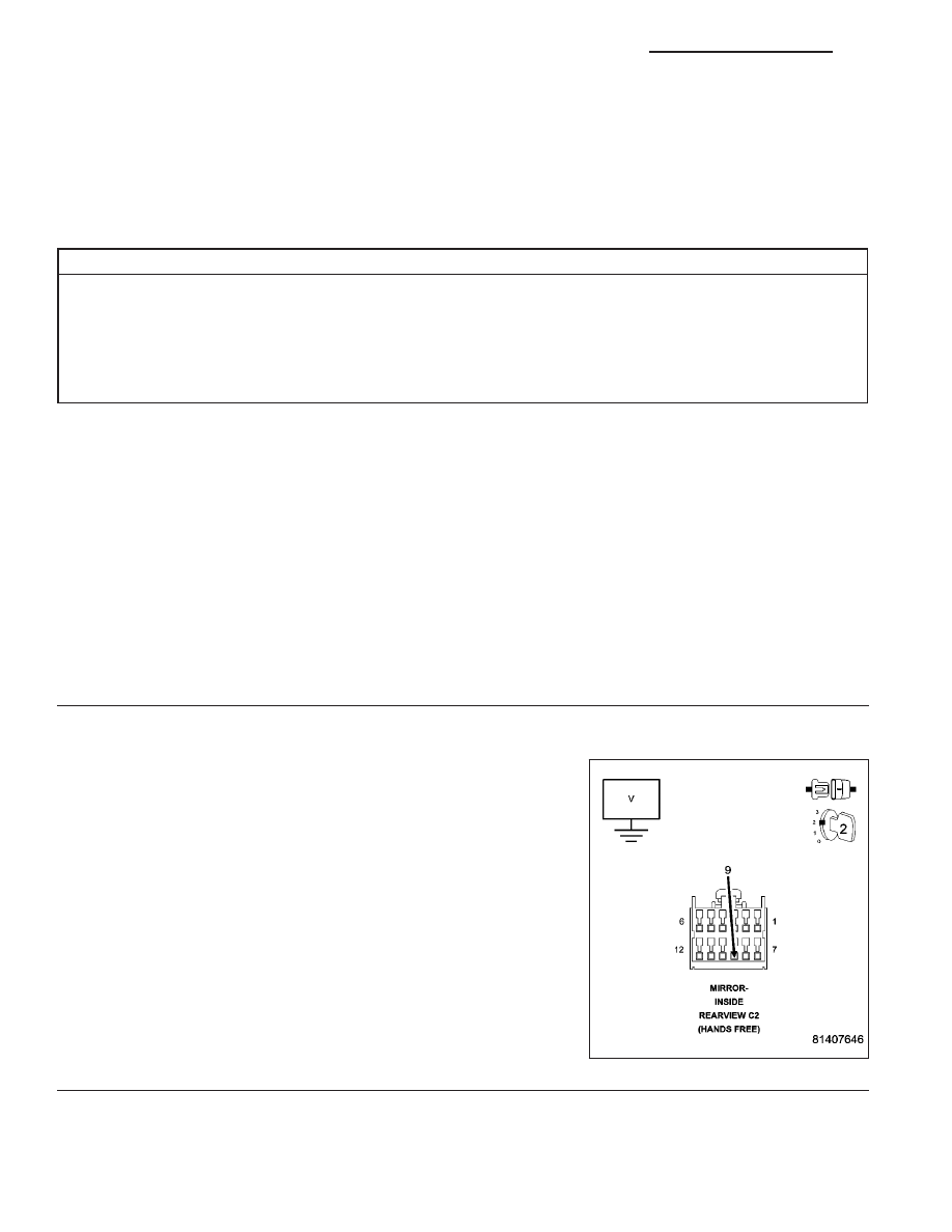
CHECK THE VOLTAGE OF THE (X730) VOICE RECOGNITION/PHONE SWITCH SIGNAL
Turn the ignition off.
Disconnect the Inside Rearview Mirror C2 harness connector.
Turn the ignition on.
Measure the voltage of the (X730) Voice Recognition/Phone Switch
Signal circuit.
Is the voltage above 5.3 volts?
Yes
>> Repair the (X730) Voice Recognition/Phone Switch Signal
circuit for a short to voltage.
Perform BODY VERIFICATION TEST - VER 1. (Refer to
BODY VERIFICATION TEST - VER 1).
No
>> Go To 3
8T - 24
NAVIGATION/TELECOMMUNICATION - ELECTRICAL DIAGNOSTICS
ND
B1437-VOICE RECOGNITION/PHONE SWITCH INPUT CIRCUIT HIGH (CONTINUED)
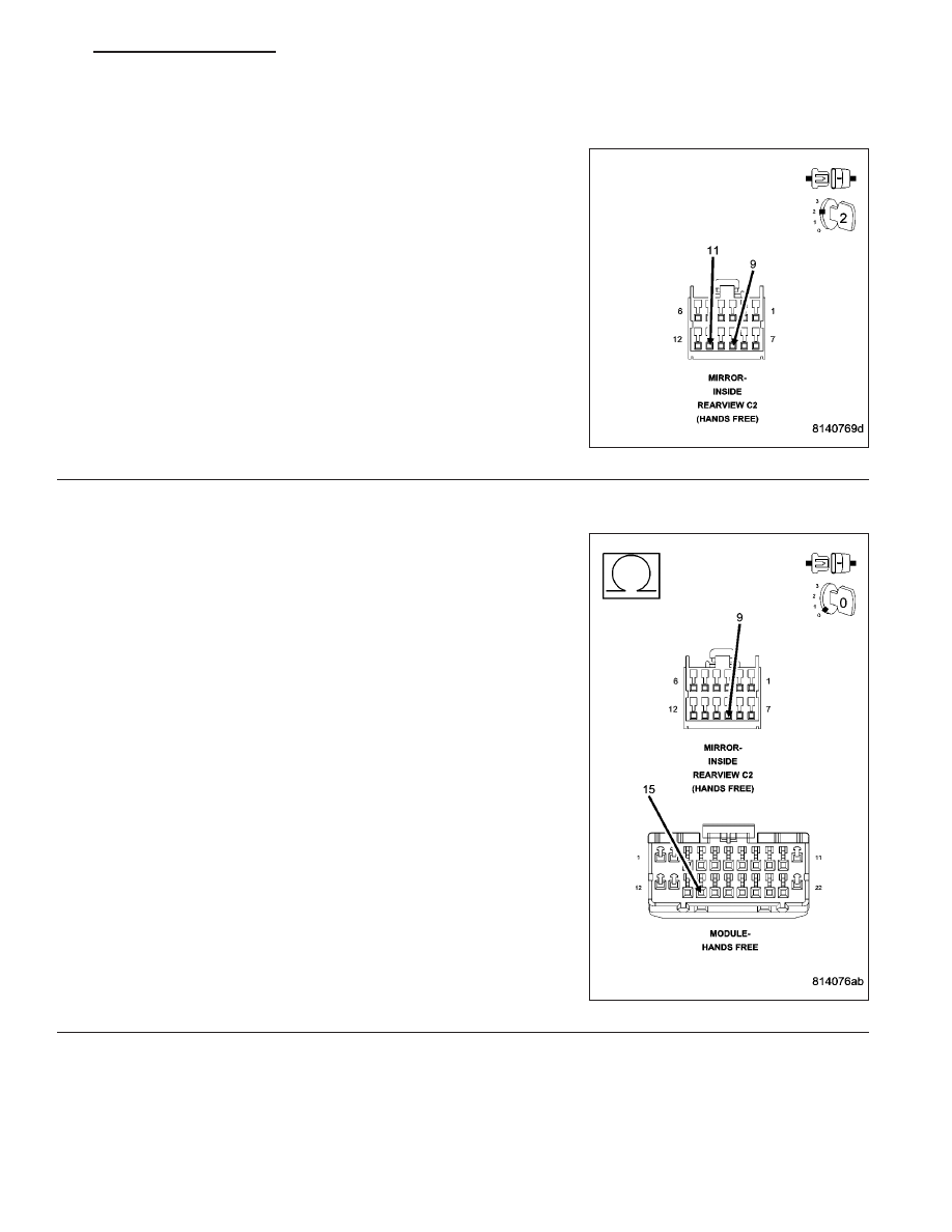
3.
INSIDE REARVIEW MIRROR
Turn the ignition off.
Connect a jumper wire between (X730) Voice Recognition/Phone
Switch Signal circuit and the (X835) Sensor Ground circuit.
Turn the ignition on.
With the scan tool, monitor the VR Phone Switch Voltage.
Is the voltage approximately 0 volts?
Yes
>> Replace the Inside Rearview Mirror in accordance with the
service information.
Perform BODY VERIFICATION TEST - VER 1. (Refer to
BODY VERIFICATION TEST - VER 1).
No
>> Go To 4
4.
(X730) VOICE RECOGNITION/PHONE SWITCH SIGNAL CIRCUIT OPEN
Turn the ignition off.
Disconnect the Hands Free Module harness connector.
Measure the resistance of the (X730) Voice Recognition/Phone Switch
Signal circuit between the HFM connector and the inside rearview mir-
ror connector.
Is the resistance below 5.0 ohms?
Yes
>> Go To 5
No
>> Repair the (X730) Voice Recognition/Phone Switch Signal
circuit for an open.
Perform BODY VERIFICATION TEST - VER 1. (Refer to
BODY VERIFICATION TEST - VER 1).
ND
NAVIGATION/TELECOMMUNICATION - ELECTRICAL DIAGNOSTICS
8T - 25
B1437-VOICE RECOGNITION/PHONE SWITCH INPUT CIRCUIT HIGH (CONTINUED)
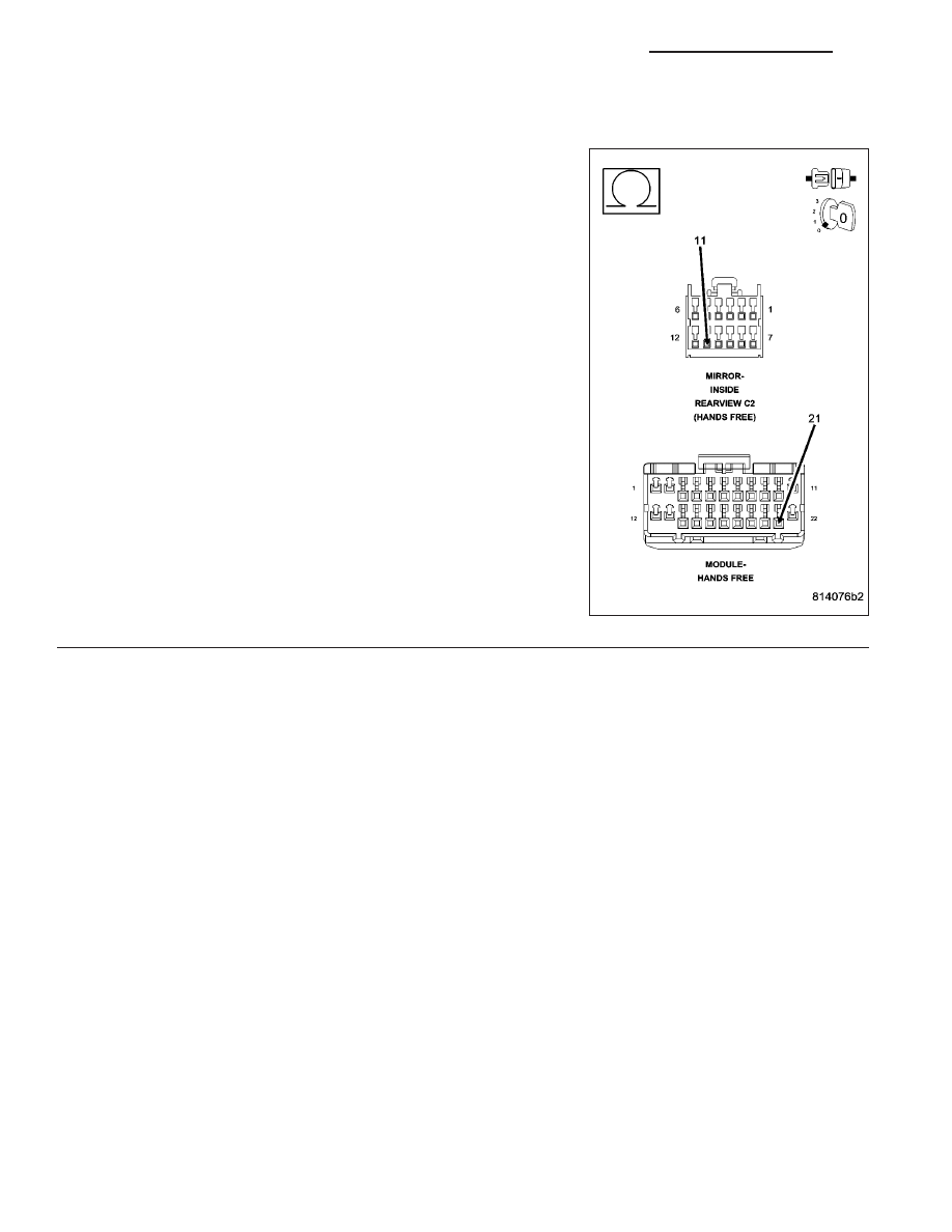
5.
(X835) SENSOR GROUND CIRCUIT OPEN
Measure the resistance of the (X835) Sensor Ground circuit between
the HFM connector and the inside rearview mirror connector.
Is the resistance below 5.0 ohms?
Yes
>> Inspect the wiring and connectors for damage or shorted
circuits. If ok, replace and program the Hands Free Mod-
ule in accordance with the service information.
Perform BODY VERIFICATION TEST - VER 1. (Refer to
BODY VERIFICATION TEST - VER 1).
No
>> Repair the (X835) Sensor Ground circuit for an open.
Perform BODY VERIFICATION TEST - VER 1. (Refer to
BODY VERIFICATION TEST - VER 1).
8T - 26
NAVIGATION/TELECOMMUNICATION - ELECTRICAL DIAGNOSTICS
ND
B1438–VOICE RECOGNITION SWITCH STUCK
ND
NAVIGATION/TELECOMMUNICATION - ELECTRICAL DIAGNOSTICS
8T - 27
Нет комментариевНе стесняйтесь поделиться с нами вашим ценным мнением.
Текст