Dodge Dakota (ND). Manual — part 797

U1412-IMPLAUSIBLE VEHICLE SPEED SIGNAL RECEIVED (CONTINUED)
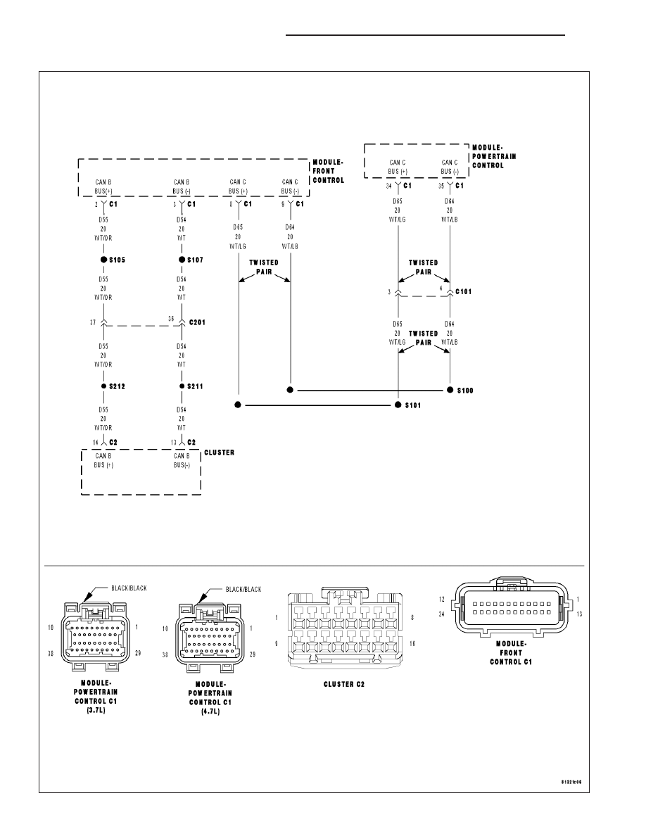
For the Engine circuit diagram (Refer to 9 - ENGINE - SCHEMATICS AND DIAGRAMS).
For a complete wiring diagram Refer to Section 8W.
•
When Monitored:
Ignition on.
•
Set Condition:
The PCM gets an implausible signal over the CAN C circuit from the ABS Module. The circuit is continuously
monitored.
Possible Causes
CAN C BUS CIRCUIT SHORTED
CAN C BUS CIRCUIT OPEN
ABS MODULE
PCM
Always perform the Pre-Diagnostic Troubleshooting procedure before proceeding. (Refer to 9 - ENGINE -
DIAGNOSIS AND TESTING).
Theory of Operation
The ABS Module sends vehicle speed information over the CAN C Bus circuit to the PCM.
Diagnostic Test
1.
ACTIVE DTC
Ignition on, engine not running.
With a scan tool, read DTCs.
Is the U1412-IMPLAUSIBLE VEHICLE SPEED SIGNAL RECEIVED active at this time?
Yes
>> Go To 2
No
>> Refer to the INTERMITTENT CONDITION Diagnostic Procedure.
Perform (NGC) POWERTRAIN VERIFICATION TEST VER - 5. (Refer to 8 - ELECTRICAL/ELEC-
TRONIC CONTROL MODULES/POWERTRAIN CONTROL MODULE - DIAGNOSIS AND TESTING)
2.
U0001-NO COMMUNICATION ON THE CAN C BUS CIRCUIT IS ACTIVE
Continue reading DTCs.
Is the U0001-NO COMMUNICATION ON THE CAN C BUS CIRCUIT ACTIVE at this time?
Yes
>> Refer to the Diagnostic Procedure for the U0001-NO COMMUNICATION ON THE CAN C BUS CIR-
CUIT.
No
>> Go To 3
9 - 726
ENGINE ELECTRICAL DIAGNOSTICS
ND
U1412-IMPLAUSIBLE VEHICLE SPEED SIGNAL RECEIVED (CONTINUED)
3.
ABS MODULE IS ACTIVE ON THE CAN C BUS
With the scan tool, select ECU View.
Verify that the ABS Module active on the bus.
Is the ABS Module active on the bus?
Yes
>> Go To 4
No
>> (Refer to 8 - ELECTRICAL/ELECTRONIC CONTROL MODULES - DIAGNOSIS AND TESTING) for No
Response diagnostic procedures.
Perform BODY VERIFICATION TEST – VER 1. (Refer to 8 - ELECTRICAL/ELECTRONIC CONTROL
MODULES/FRONT CONTROL MODULE - DIAGNOSIS AND TESTING)
4.
ACTIVE DTCS IN THE FCM
With the scan tool, select ECU View and select FCM.
Withe the scan tool, read active DTCs.
Is the U0001-NO COMMUNICATION ON THE CAN C BUS CIRCUIT ACTIVE in the FCM at this time?
Yes
>> Replace the ABS Module per Service Information.
Perform (NGC) POWERTRAIN VERIFICATION TEST VER - 5. (Refer to 8 - ELECTRICAL/ELEC-
TRONIC CONTROL MODULES/POWERTRAIN CONTROL MODULE - DIAGNOSIS AND TESTING)
No
>> Replace and program the Powertrain Control Module per Service Information.
Perform (NGC) POWERTRAIN VERIFICATION TEST VER - 5. (Refer to 8 - ELECTRICAL/ELEC-
TRONIC CONTROL MODULES/POWERTRAIN CONTROL MODULE - DIAGNOSIS AND TESTING)
ND
ENGINE ELECTRICAL DIAGNOSTICS
9 - 727
U1413-IMPLAUSIBLE ODOMETER SIGNAL RECEIVED
9 - 728
ENGINE ELECTRICAL DIAGNOSTICS
ND

U1413-IMPLAUSIBLE ODOMETER SIGNAL RECEIVED (CONTINUED)
For the Engine circuit diagram (Refer to 9 - ENGINE - SCHEMATICS AND DIAGRAMS).
For a complete wiring diagram Refer to Section 8W.
•
When Monitored:
Ignition on.
•
Set Condition:
The odometer message the PCM is receiving is implausible. The circuit is continuously monitored.
Possible Causes
CAN B OPEN OR SHORTED
CLUSTER MODULE
FRONT CONTROL MODULE
PCM
Always perform the Pre-Diagnostic Troubleshooting procedure before proceeding. (Refer to 9 - ENGINE -
DIAGNOSIS AND TESTING).
Theory of Operation
The Front Control Module isn’t receiveing an odometer signal over CAN B from the Cluster Module. The FCM has
to send the PCM an odometerl signal over CAN C. The signal the FCM is sending over CAN C is implausible.
Diagnostic Test
1.
ACTIVE DTC
Ignition on, engine not running.
With a scan tool read DTCs.
Is the DTC active at this time?
Yes
>> Go To 2
No
>> Refer to the INTERMITTENT CONDITION Diagnostic Procedure.
Perform POWERTRAIN VERIFICATION TEST. (Refer to 9 - ENGINE - STANDARD PROCEDURE)
2.
CAN B BUS HARWARE DTCS ALSO ACTIVE
With a scan tool check for DTCs in the FCM.
Are any CAN B Hardware related DTCs active at this time?
Yes
>> (Refer to 8 - ELECTRICAL/ELECTRONIC CONTROL MODULES - DIAGNOSIS AND TESTING) for the
appropriate diagnostic procedures.
Perform BODY VERIFICATION TEST – VER 1. (Refer to 8 - ELECTRICAL/ELECTRONIC CONTROL
MODULES/FRONT CONTROL MODULE - DIAGNOSIS AND TESTING)
No
>> Replace and program the Powertrain Control Module per Service Information.
Perform POWERTRAIN VERIFICATION TEST. (Refer to 9 - ENGINE - STANDARD PROCEDURE)
ND
ENGINE ELECTRICAL DIAGNOSTICS
9 - 729
Нет комментариевНе стесняйтесь поделиться с нами вашим ценным мнением.
Текст