Dodge Dakota (ND). Manual — part 175

CONDITION
POSSIBLE CAUSES
CORRECTION
CLOCK WILL NOT KEEP
SET TIME
1. Fuse inoperative.
1. Check Ignition-Off Draw (IOD) fuse in the
Integrated Power Module (IPM). Replace fuse, if
required.
2. Radio connector
damaged.
2. Check for loose or corroded radio connector.
Repair, if required.
3. Wiring damaged.
3. Check for battery voltage at radio connector.
Repair wiring, if required.
4. Radio ground faulty.
4. Check for continuity between radio chassis and
a known good ground. There should be
continuity. Repair ground, if required.
5. Radio inoperative.
5. Refer to appropriate Diagnostic Service
Information.
POOR RADIO RECEPTION
1. Antenna inoperative.
1. (Refer to 8 - ELECTRICAL/AUDIO/ANTENNA
BODY & CABLE - DIAGNOSIS AND TESTING).
2. Radio ground damaged.
2. Check for continuity between radio chassis and
a known good ground. There should be
continuity. Repair ground, if required.
3. Radio noise suppression
damaged.
3. Repair or replace ground strap as necessary.
4. Radio inoperative.
4. Refer to appropriate Diagnostic Service
Information.
SOUND DISTORTION
(VIBRATION FROM
SPEAKER AREA, BUZZING -
HUMMING)
1. Door trim panel loose or
missing fasteners.
1. Inspect door trim panel and correct as
necessary. Replace any misssing fasteners.
2. Water shield loose or
misaligned.
2. Inspect water shield and adjust as required.
3. Items placed in door trim
panel map pockets vibrating
or moving from side to side.
3. Remove items from door trim panel. Ensure
that vibration is no longer present.
NO COMPACT DISC
OPERATION
1. CD faulty.
1. Insert known good CD and test operation.
2. Foreign material on CD.
2. Clean CD and test operation.
3. Condensation on CD or
optics.
3. Allow temperature of vehicle interior to stabilize
and test operation.
4. Radio inoperative.
4. Refer to appropriate Diagnostic Service
Information.
8A - 158
AUDIO/VIDEO - SERVICE INFORMATION
ND

SPECIAL TOOLS
AUDIO SYSTEMS
ND
AUDIO/VIDEO - SERVICE INFORMATION
8A - 159
AMPLIFIER-RADIO
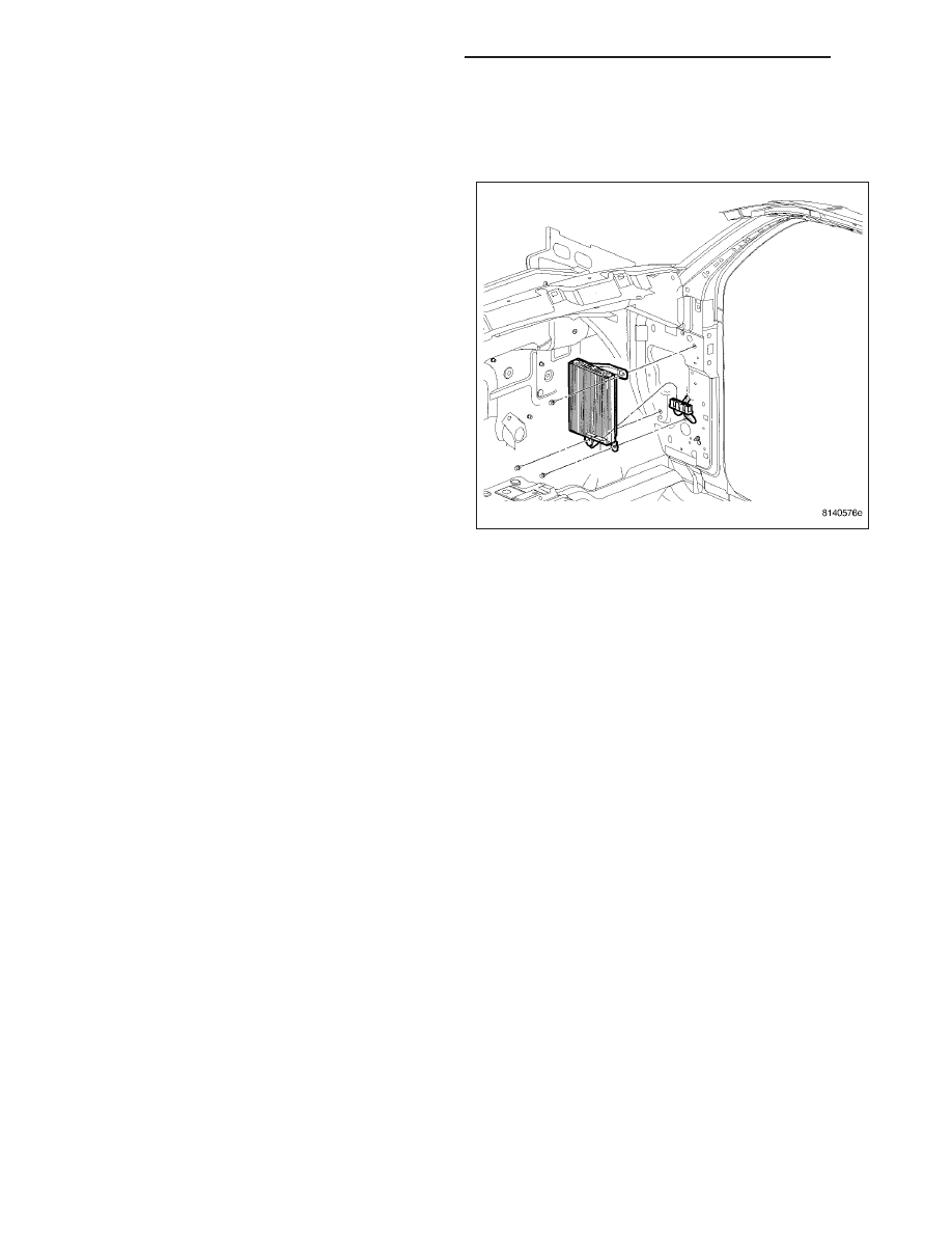
DESCRIPTION
The amplifier is a six channel unit rated at 288 watts.
The amplifier is mounted to the cowl side panel under
the passenger side of the instrument panel.
OPERATION
The amplifier receives fused battery current from a fuse in the Integrated Power Module (IPM) at all times. The
internal circuitry of the amplifier switches the amplifier on based upon a CAN bus message that is received from the
radio receiver whenever the radio is turned on. The amplifier receives the sound signal inputs from the left and right
rear outputs of the radio, then sends the amplified speaker outputs for each of those channels to the speakers.
DIAGNOSIS AND TESTING
AMPLIFIER
Any diagnosis of the Audio system should begin with the use of a scan tool and the appropriate Diagnostic
Service information.
Refer to the appropriate wiring information.
The amplifier unit should be checked if there is no sound output noted from the speakers. For diagnosis of the
power amplifier, (Refer to 8 - ELECTRICAL/AUDIO/SPEAKER - DIAGNOSIS AND TESTING).
8A - 160
AUDIO/VIDEO - SERVICE INFORMATION
ND
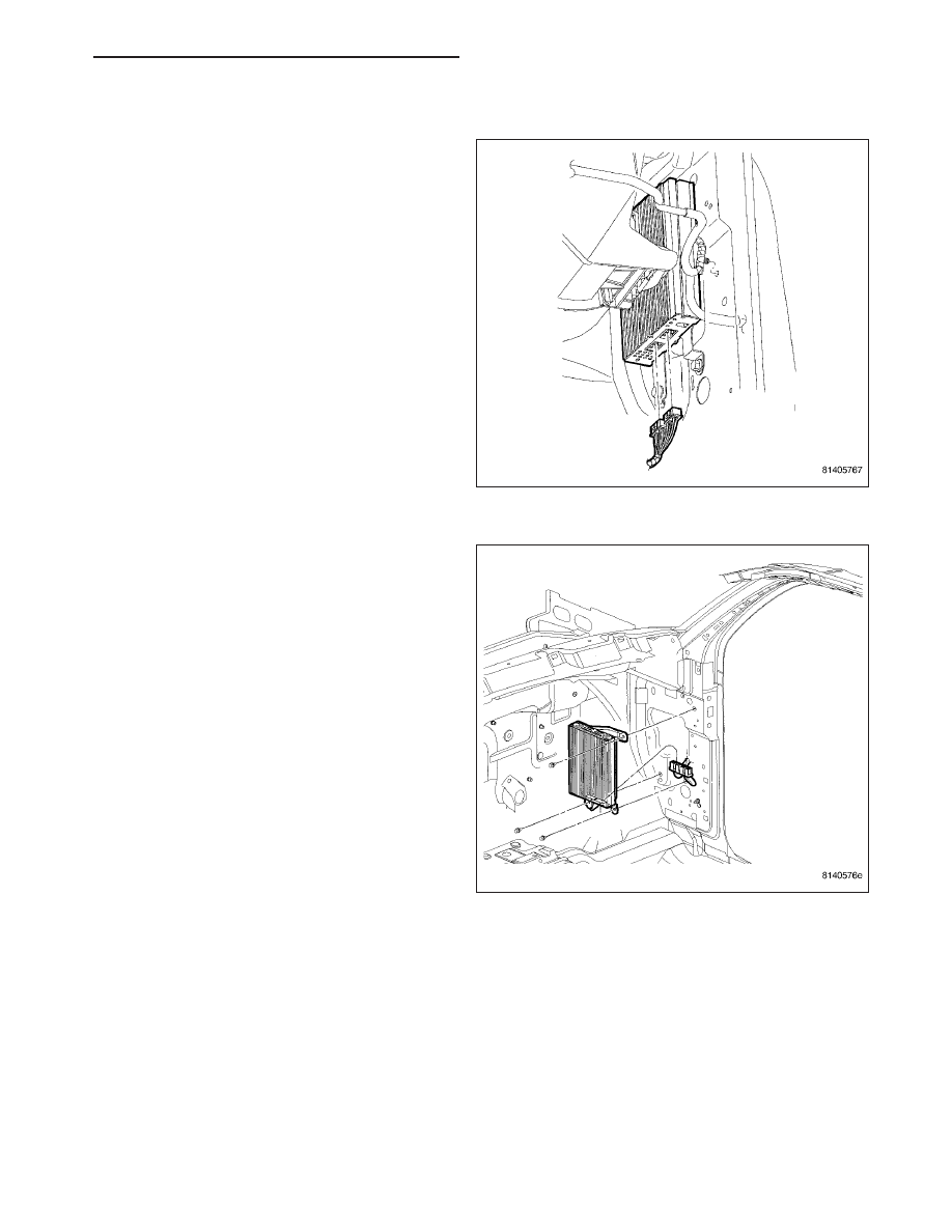
REMOVAL
1. Disconnect and isolate the battery negative cable.
2. Remove the right cowl side trim panel.
3. Disconnect electrical harness connectors.
4. Remove mounting fasteners and amplifier.
ND
AUDIO/VIDEO - SERVICE INFORMATION
8A - 161
Нет комментариевНе стесняйтесь поделиться с нами вашим ценным мнением.
Текст