Dodge Dakota (ND). Manual — part 854
INSTALLATION
CAUTION: Main bearings are select fit. (Refer to 9
-
ENGINE/ENGINE
BLOCK/CRANKSHAFT
MAIN
BEARINGS - STANDARD PROCEDURE) for proper
bearing selections.
1. Lubricate upper main bearing halves with clean
engine oil.
CAUTION: When installing crankshaft, use care
not to damage bearing surfaces on the crankshaft.
NOTE: Apply sealant to the target wheel retaining
screws prior to installation.
2. Install the crankshaft target wheel. Torque the
mounting screws to 15 N·m (12 ft. lbs.).
3. Position crankshaft in cylinder block.
4. Install the thrust washers (1).
CAUTION: The bedplate to cylinder block mateing
surface must be coated with sealant prior to
installation. Failure to do so will cause severe oil
leaks.
NOTE: The installation time to install the bedplate
after the sealant has been applied is critical.
NOTE: Make sure that the bedplate and cylinder
block sealing surfaces are clean and free of oil or
other contaminants. Contaminants on the sealing
surfaces may cause main bearing distortion and/or
oil leaks.
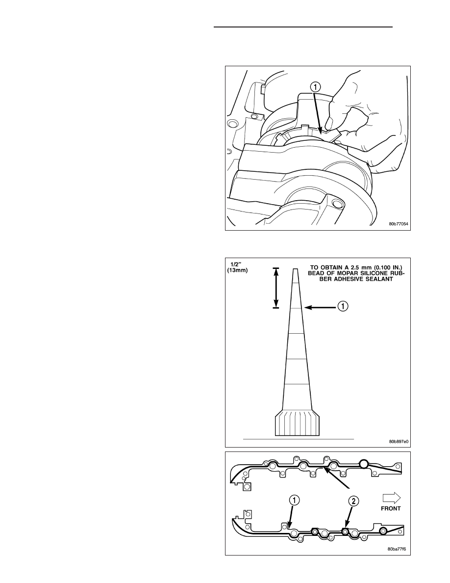
5. Apply a 2.5mm (0.100 inch) bead of Mopar
T
Gen II
Silicone Rubber Adhesive sealant (2) to the cylin-
der block-to-bedplate mating surface (1) as shown.
6. Coat the crankshaft main bearing journals with
clean engine oil and position the bedplate onto the
cylinder block.
9 - 954
ENGINE - 4.7L SERVICE INFORMATION
ND
NOTE: Lubricate the bedplate retaining bolts with clean engine oil prior to installation.
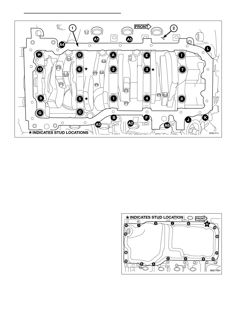
7. Install the bedplate retaining bolts, making sure to place the stud bolts in the correct location, Torque the bolts in
the sequence shown.
•
Tighten bolts A – L to 54 N·m (40 ft. lbs.)
•
Tighten bolts 1–10 to 2.8 N·m (25 in. lbs.)
•
Turn bolts 1–10 an additional 90°.
•
Tighten bolts A1– A6 to 27 N·m (20 ft. lbs.)
8. Measure crankshaft end play. (Refer to 9 - ENGINE/ENGINE BLOCK/CRANKSHAFT - STANDARD PROCE-
DURE).
9. Install the connecting rods and measure side clearance. (Refer to 9 - ENGINE/ENGINE BLOCK/CONNECTING
ROD BEARINGS - STANDARD PROCEDURE).
10. Position the oil pan gasket/windage tray, using a
new o-ring, install the oil pickup tube. Torque the
bolt to 28N·n (20 ft. lbs.) torque the nuts to 28N·m
(20 ft. lbs.).
11. Install the oil pan. Torque the retaining bolts to 15
N·m (11 ft. lbs.) in the sequence shown.
12. Install the engine (Refer to 9 - ENGINE -
INSTALLATION).
ND
ENGINE - 4.7L SERVICE INFORMATION
9 - 955
BEARINGS - CRANKSHAFT MAIN
STANDARD PROCEDURE - CRANKSHAFT MAIN BEARING - FITTING
MAIN BEARING JOURNAL DIAMETER (CRANKSHAFT REMOVED)
Crankshaft removed from the cylinder block.
Clean the oil off the main bearing journal.
Determine the maximum diameter of the journal with a micrometer. Measure at two locations 90° apart at each end
of the journal.
The maximum allowable taper is 0.008mm (0.0004 inch.) and maximum out of round is 0.005mm (0.002 inch). Com-
pare the measured diameter with the journal diameter specification (Main Bearing Fitting Chart). Select inserts
required to obtain the specified bearing-to-journal clearance.
CRANKSHAFT MAIN BEARING SELECTION
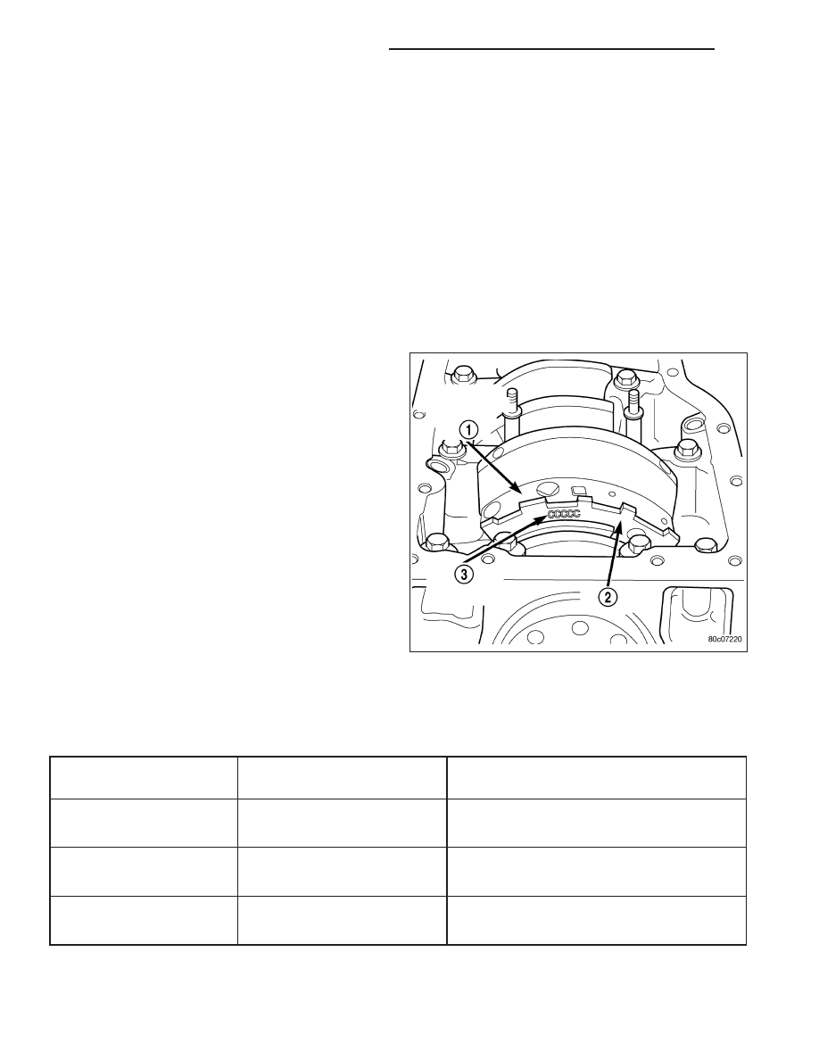
The main bearings are “select fit” to achieve proper oil
clearances. For main bearing selection, the crankshaft
position sensor target wheel has grade identification
marks stamped into it (2). These marks are read from
left to right, corresponding with journal number 1, 2, 3,
4 and 5. The crankshaft position sensor target wheel
(2) is mounted to the number 8 counter weight (1) on
the crankshaft.
NOTE: Service main bearings are coded. These codes identify what size (grade) the bearing is.
MAIN BEARING SELECTION CHART - 4.7L
GRADE
SIZE mm (in.)
FOR USE WITH
MARKING
JOURNAL SIZE
A
0.008 mm U/S
63.488–63.496 mm
(0.0004 in.) U/S
(2.4996–2.4999 in.)
B
NOMINAL
63.496–63.504 mm
(2.4999–2.5002 in.)
C
0.008 mm O/S
63.504–63.512 mm
(0.0004 in.) O/S
(2.5002–2.5005 in.)
9 - 956
ENGINE - 4.7L SERVICE INFORMATION
ND
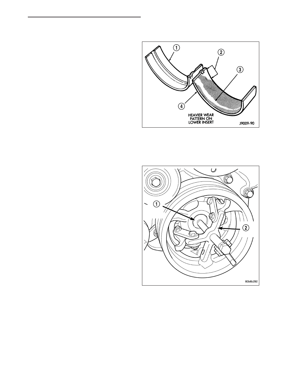
INSPECTION
Wipe the inserts clean and inspect for abnormal wear
patterns and for metal or other foreign material imbed-
ded in the lining. Normal main bearing insert wear pat-
terns are illustrated.
NOTE: If any of the crankshaft journals are scored,
the crankshaft must be repaired or replaced.
Inspect the back of the inserts for fractures, scrapings
or irregular wear patterns.
Inspect the upper insert locking tabs for damage.
Replace all damaged or worn bearing inserts.
SEAL - CRANKSHAFT OIL - FRONT
REMOVAL
1. Disconnect negative cable from battery.
2. Remove accessory drive belt (Refer to 7 - COOL-
ING/ACCESSORY
DRIVE/DRIVE
BELTS
-
REMOVAL).
3. Remove A/C compressor mouning fasteners and
set aside.
4. Drain cooling system (Refer to 7 - COOLING -
STANDARD PROCEDURE).
5. Remove upper radiator hose.
6. Disconnect electrical connector for fan mounted
inside radiator shroud.
7. Remove radiator shroud attaching fasteners.
NOTE: Transmission cooler line snaps into shroud
lower right hand corner.
8. Remove radiator cooling fan and shroud (Refer to
7
-
COOLING/ENGINE/RADIATOR
FAN
-
REMOVAL).
9. Remove crankshaft damper bolt.
10. Remove damper using Special Tools 8513 Insert
and 1026 Three Jaw Puller (2).
ND
ENGINE - 4.7L SERVICE INFORMATION
9 - 957
Нет комментариевНе стесняйтесь поделиться с нами вашим ценным мнением.
Текст