Dodge Dakota (ND). Manual — part 441
U0020-CAN B BUS OFF PERFORMANCE (CONTINUED)
For the Air Bag System circuit diagram (Refer to 8 - ELECTRICAL/RESTRAINTS - SCHEMATICS AND DIA-
GRAMS).
For a complete wiring diagram Refer to Section 8W.
•
When Monitored:
Continuously
•
Set Condition:
Whenever the CAN B Bus (+) or CAN B Bus (-) circuit is open, shorted to voltage, or shorted to ground.
Possible Causes
ACTIVE U0020 CAN B BUS DTC IN OCCUPANT CLASSIFICATION MODULE
(D55) CAN B BUS (+) CIRCUIT OPEN
(D54) CAN B BUS (-) CIRCUIT OPEN
OCCUPANT CLASSIFICATION MODULE (OCM)
Diagnostic Test
1.
VERIFY DTC U0020–CAN B BUS IS ACTIVE
Turn the ignition on.
With the scan tool, read Occupant Classification Module (OCM) DTCs.
Does the scan tool display active: U0019–CAN B BUS?
Yes
>> Go To 2
No
>> If the DTC is stored, check for an intermittent condition by inspecting the related wiring harness for
chaffed, pierced, pinched, and partially broken wires. Also, inspect the related connectors for broken,
bent, pushed out, spread, corroded, or contaminated terminals.
Perform ORC VERIFICATION TEST – VER 1.
2.
CHECK FOR ACTIVE CAN B BUS RELATED DTCS IN THE FRONT CONTROL MODULE (FCM)
With the scan tool, read Front Control Module (FCM) DTCs
Does the scan tool display any active CAN B BUS related DTCs?
Yes
>> Diagnose and repair the DTC(s). (Refer to 8 - ELECTRICAL/ELECTRONIC CONTROL MODULES -
DIAGNOSIS AND TESTING).
No
>> Go To 3
8O - 360
RESTRAINTS - ELECTRICAL DIAGNOSTICS
ND
U0020-CAN B BUS OFF PERFORMANCE (CONTINUED)
3.
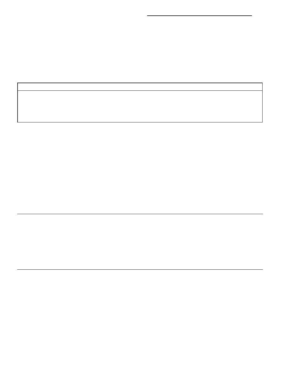
CHECK (D55) CAN B BUS (+) CIRCUIT FOR AN OPEN
Turn the ignition off.
Disconnect the negative battery cable.
Disconnect the OCM C1 connector.
Disconnect the Front Control Module (FCM) C1 connector.
Measure the resistance of the (D55) CAN B Bus (+) circuit between
the Front Control Module C1 connector and the OCM C1 connector.
Is the resistance below 2.0 ohms?
Yes
>> Go To 4
No
>> Repair the (D55) CAN B Bus (+) circuit for an open.
Perform ORC VERIFICATION TEST - VER 1.
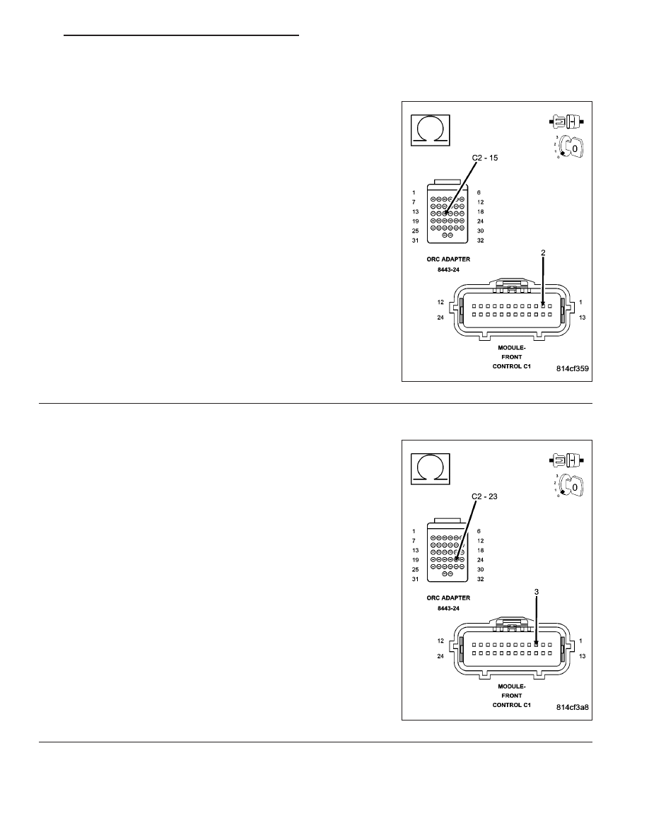
4.
CHECK (D54) CAN B BUS (–) CIRCUIT FOR AN OPEN
Measure the resistance of the (D54) CAN B Bus (–) circuit between
the Front Control Module C1 connector and the OCM C1 connector.
Is the resistance below 2.0 ohms?
Yes
>> Replace the OCM in accordance with the Service Informa-
tion.
Perform OCS VERIFICATION TEST - VER 1.
No
>> Repair the (D54) CAN B Bus (–) circuit for an open.
Perform ORC VERIFICATION TEST - VER 1.
ND
RESTRAINTS - ELECTRICAL DIAGNOSTICS
8O - 361
U0022-CAN B BUS (+) CIRCUIT LOW
For a complete wiring diagram Refer to Section 8W.
(Refer to 8 - ELECTRICAL/ELECTRONIC CONTROL MODULES - DIAGNOSIS AND TESTING) for the diagnostic
test procedure.
U0023-CAN B BUS (+) CIRCUIT HIGH
For a complete wiring diagram Refer to Section 8W.
(Refer to 8 - ELECTRICAL/ELECTRONIC CONTROL MODULES - DIAGNOSIS AND TESTING) for the diagnostic
test procedure.
U0026-CAN B BUS (-) CIRCUIT HIGH
For a complete wiring diagram Refer to Section 8W.
(Refer to 8 - ELECTRICAL/ELECTRONIC CONTROL MODULES - DIAGNOSIS AND TESTING) for the diagnostic
test procedure.
U0121-LOST COMMUNICATION WITH ANTI-LOCK BRAKE SYSTEM (ABS)
CONTROL MODULE
For a complete wiring diagram Refer to Section 8W.
(Refer to 8 - ELECTRICAL/ELECTRONIC CONTROL MODULES - DIAGNOSIS AND TESTING) for the diagnostic
test procedure.
U0141-LOST COMMUNICATION WITH FRONT CONTROL MODULE
For a complete wiring diagram Refer to Section 8W.
(Refer to 8 - ELECTRICAL/ELECTRONIC CONTROL MODULES - DIAGNOSIS AND TESTING) for the diagnostic
test procedure.
U0151-LOST COMMUNICATION WITH OCCUPANT RESTRAINT CONTROLLER
(ORC)
For a complete wiring diagram Refer to Section 8W.
(Refer to 8 - ELECTRICAL/ELECTRONIC CONTROL MODULES - DIAGNOSIS AND TESTING) for the diagnostic
test procedure.
U0154-LOST COMMUNICATION WITH OCCUPANT CLASSIFICATION MODULE
For a complete wiring diagram Refer to Section 8W.
(Refer to 8 - ELECTRICAL/ELECTRONIC CONTROL MODULES - DIAGNOSIS AND TESTING) for the diagnostic
test procedure.
U0155-LOST COMMUNICATION WITH CLUSTER/CCN
For a complete wiring diagram Refer to Section 8W.
(Refer to 8 - ELECTRICAL/ELECTRONIC CONTROL MODULES - DIAGNOSIS AND TESTING) for the diagnostic
test procedure.
U0156-LOST COMMUNICATION WITH EOM
For a complete wiring diagram Refer to Section 8W.
(Refer to 8 - ELECTRICAL/ELECTRONIC CONTROL MODULES - DIAGNOSIS AND TESTING) for the diagnostic
test procedure.
8O - 362
RESTRAINTS - ELECTRICAL DIAGNOSTICS
ND
U0164-LOST COMMUNICATION WITH HVAC CONTROL MODULE
For a complete wiring diagram Refer to Section 8W.
(Refer to 8 - ELECTRICAL/ELECTRONIC CONTROL MODULES - DIAGNOSIS AND TESTING) for the diagnostic
test procedure.
U0168-LOST COMMUNICATION WITH VEHICLE SECURITY CONTROL MODULE
(SKREEM/WCM)
For a complete wiring diagram Refer to Section 8W.
(Refer to 8 - ELECTRICAL/ELECTRONIC CONTROL MODULES - DIAGNOSIS AND TESTING) for the diagnostic
test procedure.
ND
RESTRAINTS - ELECTRICAL DIAGNOSTICS
8O - 363
Нет комментариевНе стесняйтесь поделиться с нами вашим ценным мнением.
Текст