Dodge Dakota (ND). Manual — part 804
*NO RESPONSE WITH A NO START CONDITION (CONTINUED)
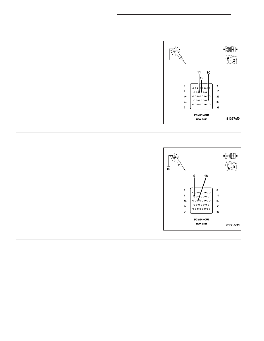
2.
(F202) (F924) PCM FUSED IGNITION SWITCH CIRCUITS
Using a 12-volt test light connected to ground, probe the PCM Fused
Ignition Switch Output circuit in the the appropriate terminals of special
tool #8815.
Does the test light illuminate brightly?
Yes
>> Go To 3
No
>> Repair the (F202) (F924) Ignition Switch Output circuit.
Inspect and replace fuses as necessary.
Perform POWERTRAIN VERIFICATION TEST. (Refer to 9
- ENGINE - STANDARD PROCEDURE)
3.
(Z913) (Z937) PCM GROUND CIRCUITS
Using a 12-volt test light connected to battery voltage, probe the
(Z913) (Z937) PCM ground circuits in the appropriate terminals of spe-
cial tool #8815.
Does the test light illuminate brightly?
Yes
>> Go To 4
No
>> Repair the PCM ground circuits.
Perform POWERTRAIN VERIFICATION TEST. (Refer to 9
- ENGINE - STANDARD PROCEDURE)
9 - 754
ENGINE ELECTRICAL DIAGNOSTICS
ND
*NO RESPONSE WITH A NO START CONDITION (CONTINUED)
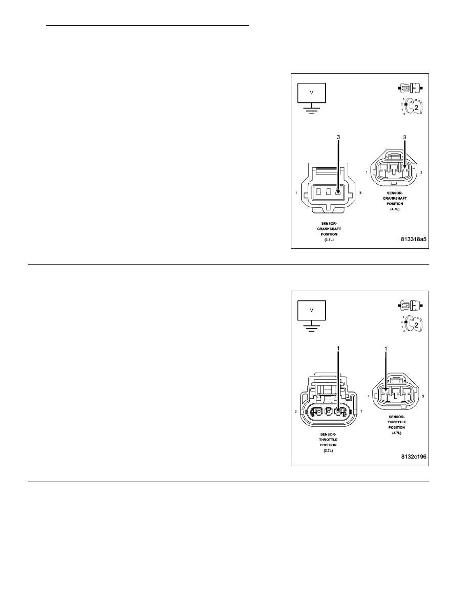
4.
(F855) 5-VOLT SUPPLY CIRCUIT
Turn the ignition off.
Connect the C2 PCM harness connector.
Disconnect the Crankshaft Position Sensor harness connector.
Ignition on, engine not running.
Measure the voltage on the (F855) 5-volt Supply circuit.
Is the voltage between 4.5 and 5.2 volts?
Yes
>> Go To 5
No
>> Go To 6
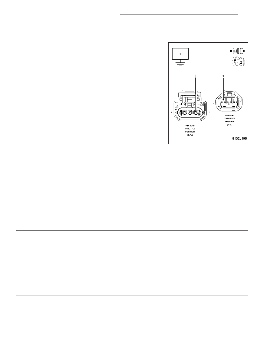
5.
CKP SENSOR
Turn the ignition off.
Disconnect the TP Sensor harness connector.
Ignition on, engine not running.
Measure the voltage on the (F855) 5-volt Supply circuit in the TP Sen-
sor harness connector.
Is the voltage between 4.5 and 5.2 volts?
Yes
>> If communication is available with a PCM on a like vehicle,
replace and program the Powertrain Control Module per
Service Information.
Perform POWERTRAIN VERIFICATION TEST. (Refer to 9
- ENGINE - STANDARD PROCEDURE)
No
>> Replace the Crankshaft Position Sensor.
Perform POWERTRAIN VERIFICATION TEST. (Refer to 9
- ENGINE - STANDARD PROCEDURE)
ND
ENGINE ELECTRICAL DIAGNOSTICS
9 - 755
*NO RESPONSE WITH A NO START CONDITION (CONTINUED)
6.
(F855) 5-VOLT SENSOR OPEN/SHORTED
Turn the ignition off.
Disconnect the TP Sensor/Throttle Body harness connector.
Ignition on, engine not running.
Measure the voltage on the (F855) 5-volt Supply circuit.
Disconnect all the sensors that use the (F855) 5-volt Supply circuit.
Did the voltage return to 4.5 to 5.2 volts when disconnecting
any of the sensors.
Yes
>> Replace the sensor that is pulling down the (F855) 5-volt
supply.
Perform POWERTRAIN VERIFICATION TEST. (Refer to 9
- ENGINE - STANDARD PROCEDURE)
No
>> Go To 7
7.
(F855) 5-VOLT SUPPLY CIRCUIT SHORTED TO GROUND
Turn the ignition off.
Disconnect C1 and C2 PCM harness connectors.
Disconnect all the sensors that share the (F855) 5-volt Supply circuit.
Measure the resistance between ground and the (F855) 5-volt Supply circuit at one of the sensor harness connec-
tors.
Is the resistance below 100 ohms?
Yes
>> Repair the short to ground in the (F855) 5-volt Supply circuit.
Perform POWERTRAIN VERIFICATION TEST. (Refer to 9 - ENGINE - STANDARD PROCEDURE)
No
>> Go To 8
8.
(F856) 5-VOLT SUPPLY CIRCUIT SHORTED TO GROUND
Disconnect all the sensors that share the (F856) 5-volt Supply circuit.
Measure the resistance between ground and the (F856) 5-volt Supply circuit at one of the sensor harness connec-
tors.
Is the resistance below 100 ohms?
Yes
>> Repair the short to ground in the (F856) 5-volt Supply circuit.
Perform POWERTRAIN VERIFICATION TEST. (Refer to 9 - ENGINE - STANDARD PROCEDURE)
No
>> Go To 9
9 - 756
ENGINE ELECTRICAL DIAGNOSTICS
ND
*NO RESPONSE WITH A NO START CONDITION (CONTINUED)
9.
PCM
NOTE: Before continuing, check the PCM harness connector terminals for corrosion, damage, or terminal
push out. Repair as necessary.
Using the schematics as a guide, inspect the wire harness and connectors. Pay particular attention to all Power and
Ground circuits.
Were there any problems found?
Yes
>> Repair as necessary.
Perform (NGC) POWERTRAIN VERIFICATION TEST. (Refer to 9 - ENGINE - STANDARD PROCE-
DURE)
No
>> Replace and program the Powertrain Control Module per Service Information.
Perform (NGC) POWERTRAIN VERIFICATION TEST. (Refer to 9 - ENGINE - STANDARD PROCE-
DURE)
ND
ENGINE ELECTRICAL DIAGNOSTICS
9 - 757
Нет комментариевНе стесняйтесь поделиться с нами вашим ценным мнением.
Текст