Dodge Dakota (ND). Manual — part 770
P1603-PCM INTERNAL DUAL-PORT RAM COMMUNICATION FAILURE (CONTINUED)
2.
PCM
The Powertrain Control Module is reporting internal errors.
NOTE: Before continuing, check the PCM harness connector terminals for corrosion, damage, or terminal
push out. Repair as necessary.
Using the schematics as a guide, inspect the wire harness and connectors. Pay particular attention to all Power and
Ground circuits.
Were there any problems found?
Yes
>> Repair as necessary.
Perform POWERTRAIN VERIFICATION TEST. (Refer to 9 - ENGINE - STANDARD PROCEDURE)
No
>> Replace and program the Powertrain Control Module per Service Information.
Perform POWERTRAIN VERIFICATION TEST. (Refer to 9 - ENGINE - STANDARD PROCEDURE)
9 - 618
ENGINE ELECTRICAL DIAGNOSTICS
ND
P1604-PCM INTERNAL DUAL-PORT RAM READ/WRITE INTEGRITY FAILURE
For the Engine circuit diagram (Refer to 9 - ENGINE - SCHEMATICS AND DIAGRAMS).
For a complete wiring diagram Refer to Section 8W.
•
When Monitored:
Ignition on and battery voltage greater than 10 volts.
•
Set Condition:
Internal PCM failure detected. One Trip Fault. Three good trips to turn off the MIL.
Possible Causes
PCM FUSED IGNITION SWITCH CIRCUIT
PCM INTERNAL
Always perform the Pre-Diagnostic Troubleshooting procedure before proceeding. (Refer to 9 - ENGINE -
DIAGNOSIS AND TESTING).
Diagnostic Test
1.
PCM IGNITION CIRCUITS
Turn the ignition off.
Disconnect the C1 PCM harness connector.
Ignition on, engine not running.
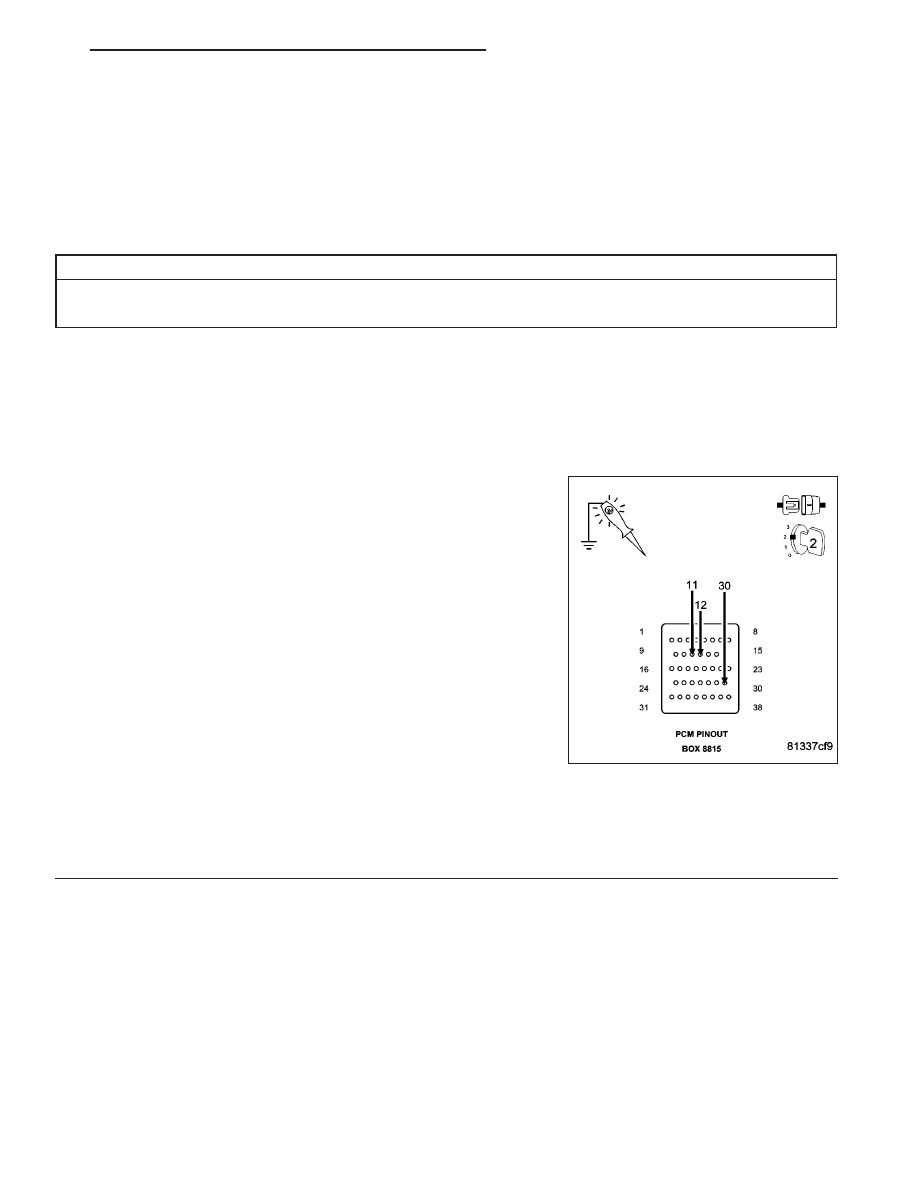
CAUTION: Do not probe the PCM harness connectors. Probing
the PCM harness connectors will damage the PCM terminals
resulting in poor terminal to pin connection. Install Miller Special
Tool #8815 to perform diagnosis.
With a 12-volt test light connected to ground and with special tool
#8815 installed, probe the (F202) and (F924) Fused Ignition Switch
circuits.
Perform the above check with the Ignition key in the off lock position,
Ignition on, engine not running position, and during cranking.
Wiggle the related wire harness while probing the special tool with the
test light to try to interrupt the circuit.
Does the test light illuminate brightly?
Yes
>> Go To 2
No
>> Repair the open or excessive resistance in the (F202) and (F924) Fused Ignition Switch (Offf, Run,
Start) circuits. Inspect the related fuse, if the fuse is open check the circuits for a short to ground.
Perform POWERTRAIN VERIFICATION TEST. (Refer to 9 - ENGINE - STANDARD PROCEDURE)
ND
ENGINE ELECTRICAL DIAGNOSTICS
9 - 619
P1604-PCM INTERNAL DUAL-PORT RAM READ/WRITE INTEGRITY FAILURE (CONTINUED)
2.
PCM
The Powertrain Control Module is reporting internal errors.
NOTE: Before continuing, check the PCM harness connector terminals for corrosion, damage, or terminal
push out. Repair as necessary.
Using the schematics as a guide, inspect the wire harness and connectors. Pay particular attention to all Power and
Ground circuits.
Were there any problems found?
Yes
>> Repair as necessary.
Perform POWERTRAIN VERIFICATION TEST. (Refer to 9 - ENGINE - STANDARD PROCEDURE)
No
>> Replace and program the Powertrain Control Module per Service Information.
Perform POWERTRAIN VERIFICATION TEST. (Refer to 9 - ENGINE - STANDARD PROCEDURE)
9 - 620
ENGINE ELECTRICAL DIAGNOSTICS
ND
P1607-PCM INTERNAL SHUTDOWN TIMER RATIONALITY
For the Engine circuit diagram (Refer to 9 - ENGINE - SCHEMATICS AND DIAGRAMS).
For a complete wiring diagram Refer to Section 8W.
•
When Monitored:
Ignition on and battery voltage greater than 10 volts.
•
Set Condition:
Internal PCM failure detected. One Trip Fault. Three good trips to turn off the MIL.
Possible Causes
PCM FUSED IGNITION SWITCH CIRCUIT
PCM INTERNAL
Always perform the Pre-Diagnostic Troubleshooting procedure before proceeding. (Refer to 9 - ENGINE -
DIAGNOSIS AND TESTING).
Diagnostic Test
1.
PCM IGNITION CIRCUITS
Turn the ignition off.
Disconnect the C1 PCM harness connector.
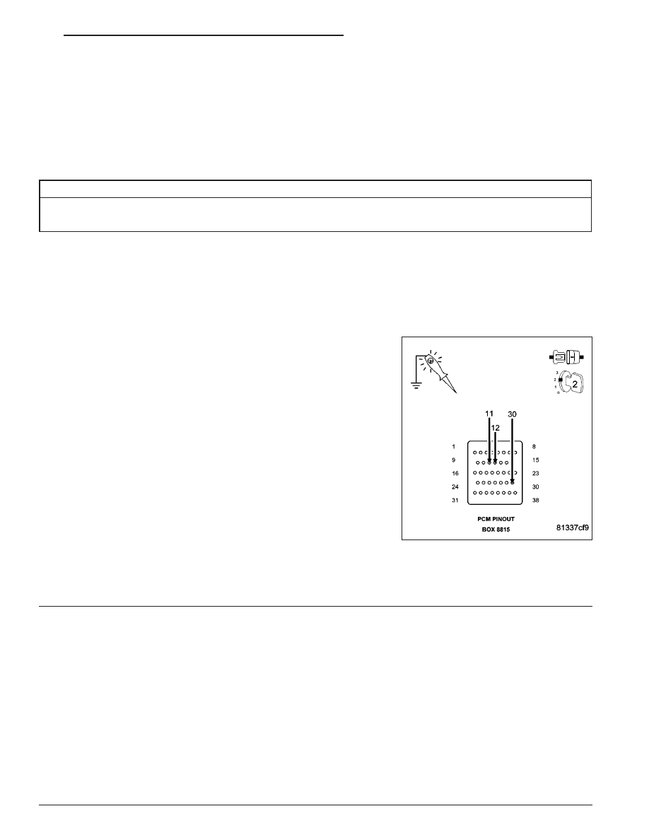
CAUTION: Do not probe the PCM harness connectors. Probing
the PCM harness connectors will damage the PCM terminals
resulting in poor terminal to pin connection. Install Miller Special
Tool #8815 to perform diagnosis.
With a 12-volt test light connected to ground and with special tool
#8815 installed, probe the (F202) and (F924) Fused Ignition Switch
circuits.
Perform the above check with the Ignition key in the off lock position,
Ignition on, engine not running position, and during cranking.
Wiggle the related wire harness while probing the special tool with the
test light to try to interrupt the circuit.
Does the test light illuminate brightly?
Yes
>> Go To 2
No
>> Repair the open or excessive resistance in the (F202) and (F924) Fused Ignition Switch (Offf, Run,
Start) circuits. Inspect the related fuse, if the fuse is open check the circuits for a short to ground.
Perform POWERTRAIN VERIFICATION TEST. (Refer to 9 - ENGINE - STANDARD PROCEDURE)
2.
PCM
The Powertrain Control Module is reporting internal errors.
NOTE: Before continuing, check the PCM harness connector terminals for corrosion, damage, or terminal
push out. Repair as necessary.
Using the schematics as a guide, inspect the wire harness and connectors. Pay particular attention to all Power and
Ground circuits.
Were there any problems found?
Yes
>> Repair as necessary.
Perform POWERTRAIN VERIFICATION TEST. (Refer to 9 - ENGINE - STANDARD PROCEDURE)
No
>> Replace and program the Powertrain Control Module per Service Information.
Perform POWERTRAIN VERIFICATION TEST. (Refer to 9 - ENGINE - STANDARD PROCEDURE)
ND
ENGINE ELECTRICAL DIAGNOSTICS
9 - 621
Нет комментариевНе стесняйтесь поделиться с нами вашим ценным мнением.
Текст