Dodge Dakota (ND). Manual — part 1256
B105B–RECIRCULATION DOOR CONTROL CIRCUIT OPEN
24 - 22
HVAC - ELECTRICAL DIAGNOSTICS
ND

B105B–RECIRCULATION DOOR CONTROL CIRCUIT OPEN (CONTINUED)
For the Manual Temperature Control (MTC) circuit diagram (Refer to 24 - HEATING & AIR CONDITIONING - SCHE-
MATICS AND DIAGRAMS).
For a complete wiring diagram Refer to Section 8W.
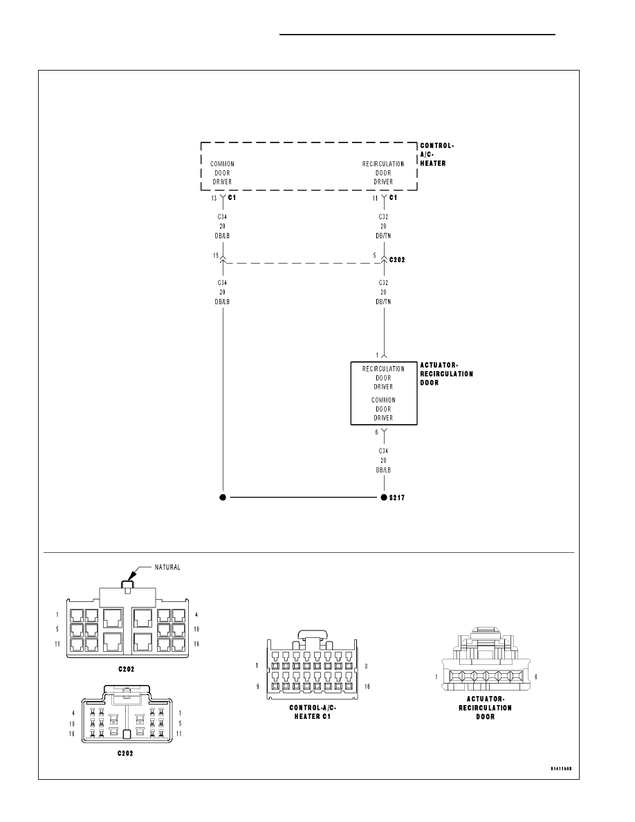
Theory of Operation
The A/C Heater Control drives the Recirculation Door Actuator via the (C32) Recirculation Door Driver circuit and
the (C34) Common Door Driver circuit. All of the door actuators share the (C34) Common Door Driver. Inside the
A/C Heater Control, each door actuator has its own unique driver, but all share a single common door driver circuit.
Due to the shared circuitry similar DTCs can set at the same time for multiple actuators depending upon the location
of the open circuit and the direction the actuator is moving when the open is present.
•
When Monitored:
When actuator movement is requested.
•
Set Condition:
If Recirculation Door Actuator’s electrical circuit is open. This DTC has a maturing time of 5 seconds and a
de-maturing time of 10 seconds. If the DTC’s status changes from active to stored it will stay in memory for
100 ignition cycles.
Possible Causes
(C32) RECIRCULATION DOOR DRIVER CIRCUIT OPEN
(C34) COMMON DOOR DRIVER CIRCUIT OPEN
RECIRCULATION DOOR ACTUATOR
A/C HEATER CONTROL
NOTE: DTC B105B must be active for the results of this test to be valid. Do not perform this test if DTC
B105B is stored. Refer to HVAC System Test for stored DTC test procedures.
Diagnostic Test
1.
CHECK FOR ACTIVE CONTROL CIRCUIT/PERFORMANCE DTCs
Turn the ignition on.
With the scan tool, read active HVAC DTCs.
Does the scan tool display any active: XXXX CONTROL CIRCUIT/PERFORMANCE DTCs?
Yes
>> Diagnose and repair the DTC(s). Refer to the Table of Contents in this Section for a complete list of all
HVAC related symptoms.
No
>> Go To 2
ND
HVAC - ELECTRICAL DIAGNOSTICS
24 - 23
B105B–RECIRCULATION DOOR CONTROL CIRCUIT OPEN (CONTINUED)
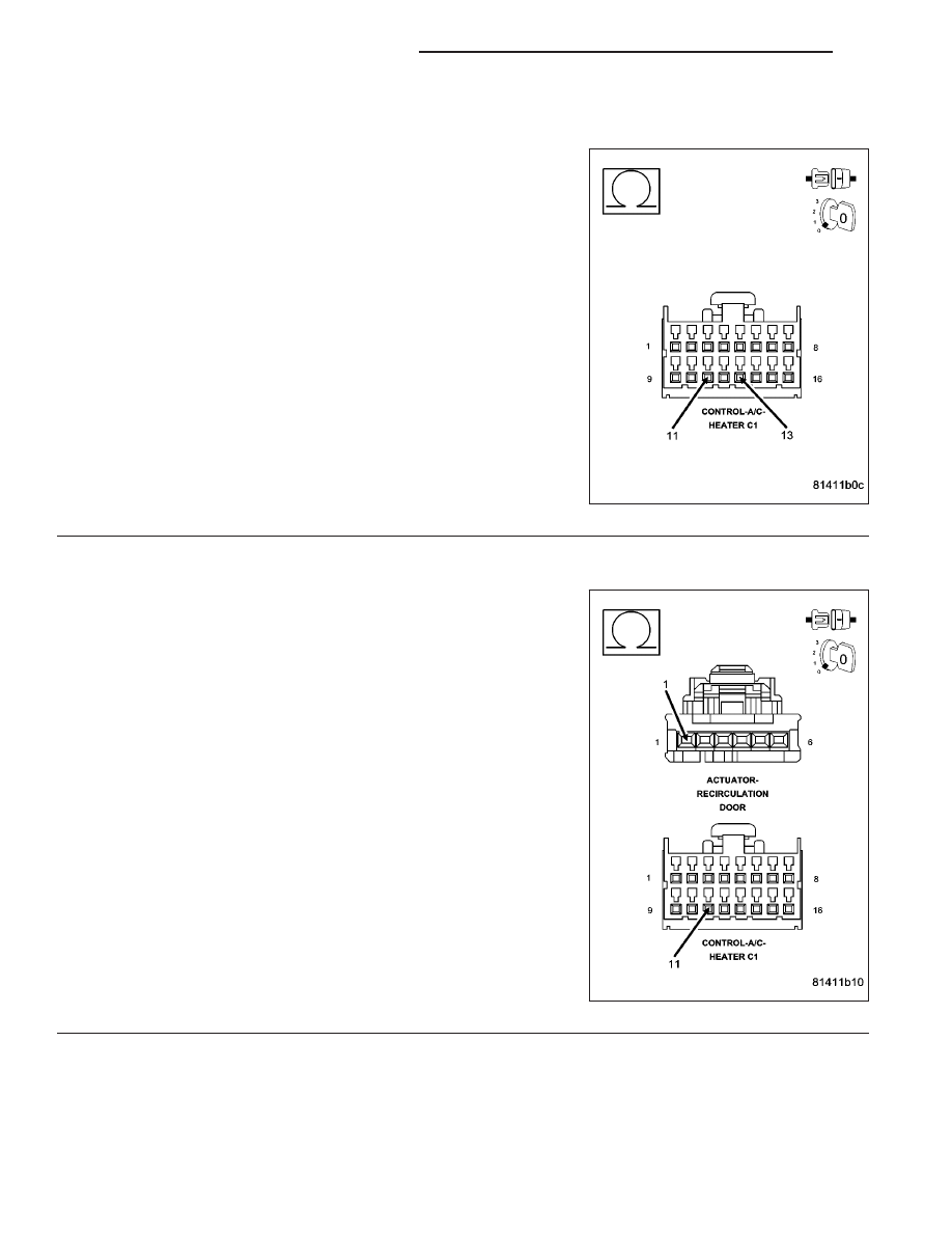
2.
CHECK RECIRCULATION DOOR ACTUATOR CIRCUIT RESISTANCE
Turn the ignition off.
Disconnect the A/C Heater Control C1 harness connector.
Measure the resistance between the (C32) Recirculation Door Driver
circuit and the (C34) Common Door Driver circuit in the A/C Heater
Control C1 harness connector.
Is the resistance above 55 ohms?
Yes
>> Go To 3
No
>> Replace the A/C Heater Control in accordance with the
Service Information.
Perform BODY VERIFICATION TEST - VER 1. (Refer to 8
-
ELECTRICAL/ELECTRONIC
CONTROL
MODULES/
FRONT
CONTROL
MODULE
-
DIAGNOSIS
AND
TESTING).
3.
CHECK (C32) RECIRCULATION DOOR DRIVER CIRCUIT FOR AN OPEN
Disconnect the Recirculation Door Actuator harness connector.
Measure the resistance of the (C32) Recirculation Door Driver circuit
between the A/C Heater Control C1 harness connector and the Recir-
culation Door Actuator harness connector.
Is the resistance below 5.0 ohms?
Yes
>> Go To 4
No
>> Repair the (C32) Recirculation Door Driver circuit for an
open.
Perform BODY VERIFICATION TEST - VER 1. (Refer to 8
-
ELECTRICAL/ELECTRONIC
CONTROL
MODULES/
FRONT
CONTROL
MODULE
-
DIAGNOSIS
AND
TESTING).
24 - 24
HVAC - ELECTRICAL DIAGNOSTICS
ND
B105B–RECIRCULATION DOOR CONTROL CIRCUIT OPEN (CONTINUED)
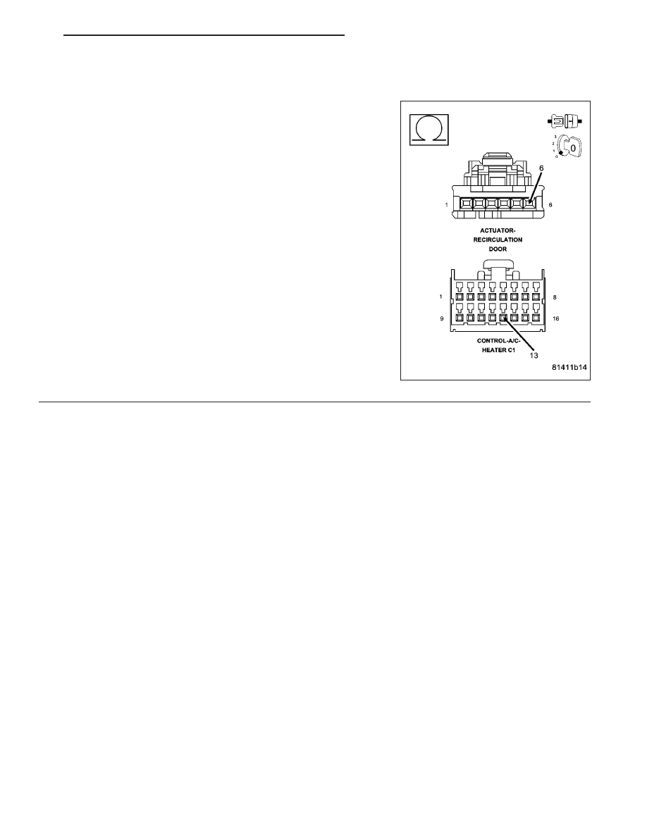
4.
CHECK (C34) COMMON DOOR DRIVER CIRCUIT FOR AN OPEN
Measure the resistance of the (C34) Common Door Driver circuit
between the A/C Heater Control C1 harness connector and the Recir-
culation Door Actuator harness connector.
Is the resistance below 5.0 ohms?
Yes
>> Replace the Recirculation Door Actuator in accordance
with the Service Information.
Perform BODY VERIFICATION TEST - VER 1. (Refer to 8
-
ELECTRICAL/ELECTRONIC
CONTROL
MODULES/
FRONT CONTROL MODULE - DIAGNOSIS AND TEST-
ING).
No
>> Repair the (C34) Common Door Driver circuit for an open.
Perform BODY VERIFICATION TEST - VER 1. (Refer to 8
-
ELECTRICAL/ELECTRONIC
CONTROL
MODULES/
FRONT
CONTROL
MODULE
-
DIAGNOSIS
AND
TESTING).
ND
HVAC - ELECTRICAL DIAGNOSTICS
24 - 25
Нет комментариевНе стесняйтесь поделиться с нами вашим ценным мнением.
Текст