Dodge Dakota (ND). Manual — part 122
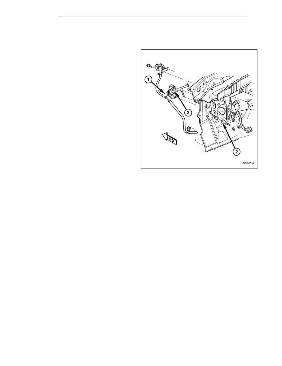
CLUTCH PEDAL POSITION SWITCH
DIAGNOSIS AND TESTING
NOTE: The clutch pedal position switch prevents
the starter motor engagement unless the clutch
pedal is depressed. Input from the switch is used
to shut down/prevent operation of speed control
system when the clutch pedal is depressed.
1. Disconnect switch 2-wire connector (2) under
instrument panel.
2. Check switch (3) continuity with an ohmmeter while
operating clutch pedal.
•
Pedal Depressed - Continuity
•
Pedal Released - No Continuity
3. If continuity is not present or always present,
replace clutch master cylinder (1). Switch is not
serviced separately.
6 - 14
CLUTCH
ND
COOLING
TABLE OF CONTENTS
page
page
COOLING
. . . . . . . . . . . . . . . . . . . . . . . . . . 2
. . . . . . . . . . . . . . . . . . . . . . . . . . . . 3
COOLING SYSTEM - TESTING FOR LEAKS
. . . . . . . . . . . . . . . . . 5
ENGINES . . . . . . . . . . . . . . . . . . . . . . . . . . . . 13
. . . . . . . . . . . . . . . 14
COOLING SYSTEM CLEANING/REVERSE
FLUSHING . . . . . . . . . . . . . . . . . . . . . . . . . . . 14
. . . . . . . . . . . . . . . . . . . . . . . . . . . . 15
. . . . . . . . . . . . . . . . . . . . . . . 15
. . . . . . . . . . . . . . . . . . . . . . . . . . . 16
. . . . . . . . . . . . . . . . . . . . . . 17
. . . . . . . . . . . . . . . . . . . . . . . . . . . . . . . 23
. . . . . . . . . . . . . . . . . . . . . . . . . 49
ND
COOLING
7 - 1
COOLING
DESCRIPTION
The cooling system regulates engine operating temperature. It allows the engine to reach normal operating temper-
ature as quickly as possible. It also maintains normal operating temperature and prevents overheating.
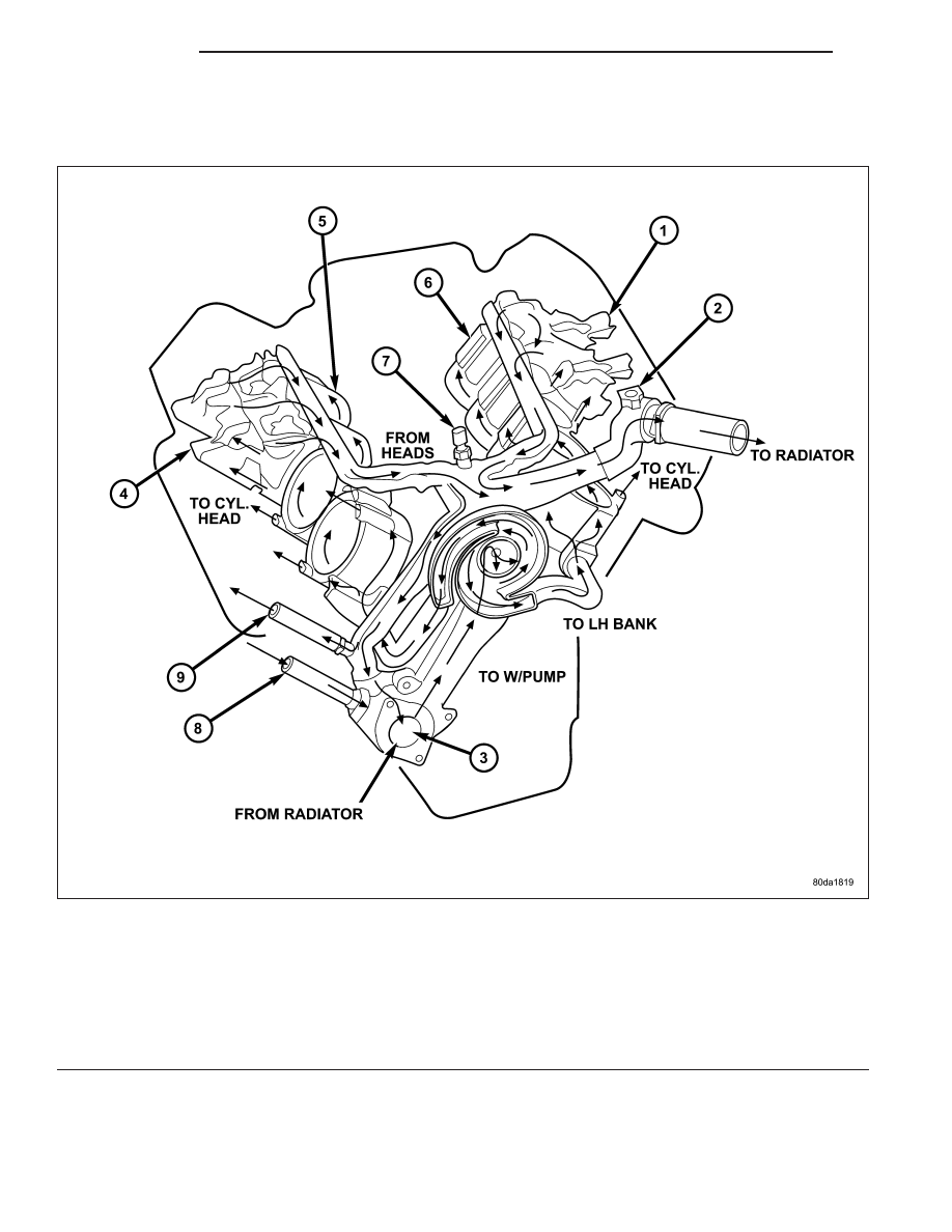
Engine Cooling System Flow - 3.7L/4.7L
1 - LH CYL. HEAD
2 - BLEED
3 - THERMOSTAT LOCATION
4 - RH CYL. HEAD
5 - RH BANK CYL. BLOCK
6 - LH BANK CYL. BLOCK
7 - COOLANT TEMP. SENSOR
8 - FROM HEATER CORE
9 - TO HEATER CORE
7 - 2
COOLING
ND
The cooling system provides a means of heating the passenger compartment and cooling the automatic transmis-
sion fluid (if equipped). The cooling system is pressurized and uses a centrifugal water pump to circulate coolant
through the system. The coolant recovery/reserve system utilizes an ambient overflow bottle.
•
Radiator
•
Cooling fan (mechanical/Electrical)
•
Thermal viscous fan drive
•
Fan shroud
•
Radiator pressure cap
•
Thermostat
•
Coolant reserve/overflow system
•
Transmission oil cooler (if equipped with an automatic transmission)
•
Coolant
•
Water pump
•
Hoses and hose clamps
OPERATION
The cooling system regulates engine operating temperature. It allows the engine to reach normal operating temper-
ature as quickly as possible. It also maintains normal operating temperature and prevents overheating.
The cooling system also provides a source of hot water (coolant) for heating the passenger compartment. The cool-
ing system is pressurized and uses a centrifugal water pump to circulate coolant throughout the system.
•
When engine is cold the thermostat is closed. The cooling system has no flow through the radiator. The cool-
ant flows through the engine, water pump, and heater.
•
When engine is warm the thermostat is full open. The coolant flows through the radiator, heater, and water
pump.
All engines utilize an ambient overflow bottle for coolant recovery/reserve.
An optional factory installed maximum duty cooling package is available on most models. This package will provide
additional cooling capacity for vehicles used under extreme conditions such as trailer towing in high ambient
temperatures.
DIAGNOSIS AND TESTING
ON-BOARD DIAGNOSTICS (OBD)
COOLING SYSTEM RELATED DIAGNOSTICS
The powertrain control module (PCM) has been programmed to monitor certain cooling system components:
•
If the engine has remained cool for too long a period, such as with a stuck open thermostat, a Diagnostic
Trouble Code (DTC) can be set.
•
If an open or shorted condition has developed in the relay circuit controlling the electric radiator fan, a Diag-
nostic Trouble Code (DTC) can be set.
If the problem is sensed in a monitored circuit often enough to indicated an actual problem, a DTC is stored. The
DTC will be stored in the PCM memory for eventual display to the service technician. (Refer to 25 - EMISSIONS
CONTROL - DESCRIPTION).
ACCESSING DIAGNOSTIC TROUBLE CODES
To read DTC’s and to obtain cooling system data, (Refer to 25 - EMISSIONS CONTROL - DESCRIPTION).
ERASING TROUBLE CODES
After the problem has been repaired, use the scan tool to erase a DTC. Refer to the appropriate Powertrain Diag-
nostic Procedures service information for operation of the scan tool.
ND
COOLING
7 - 3
Нет комментариевНе стесняйтесь поделиться с нами вашим ценным мнением.
Текст