Dodge Dakota (ND). Manual — part 1108
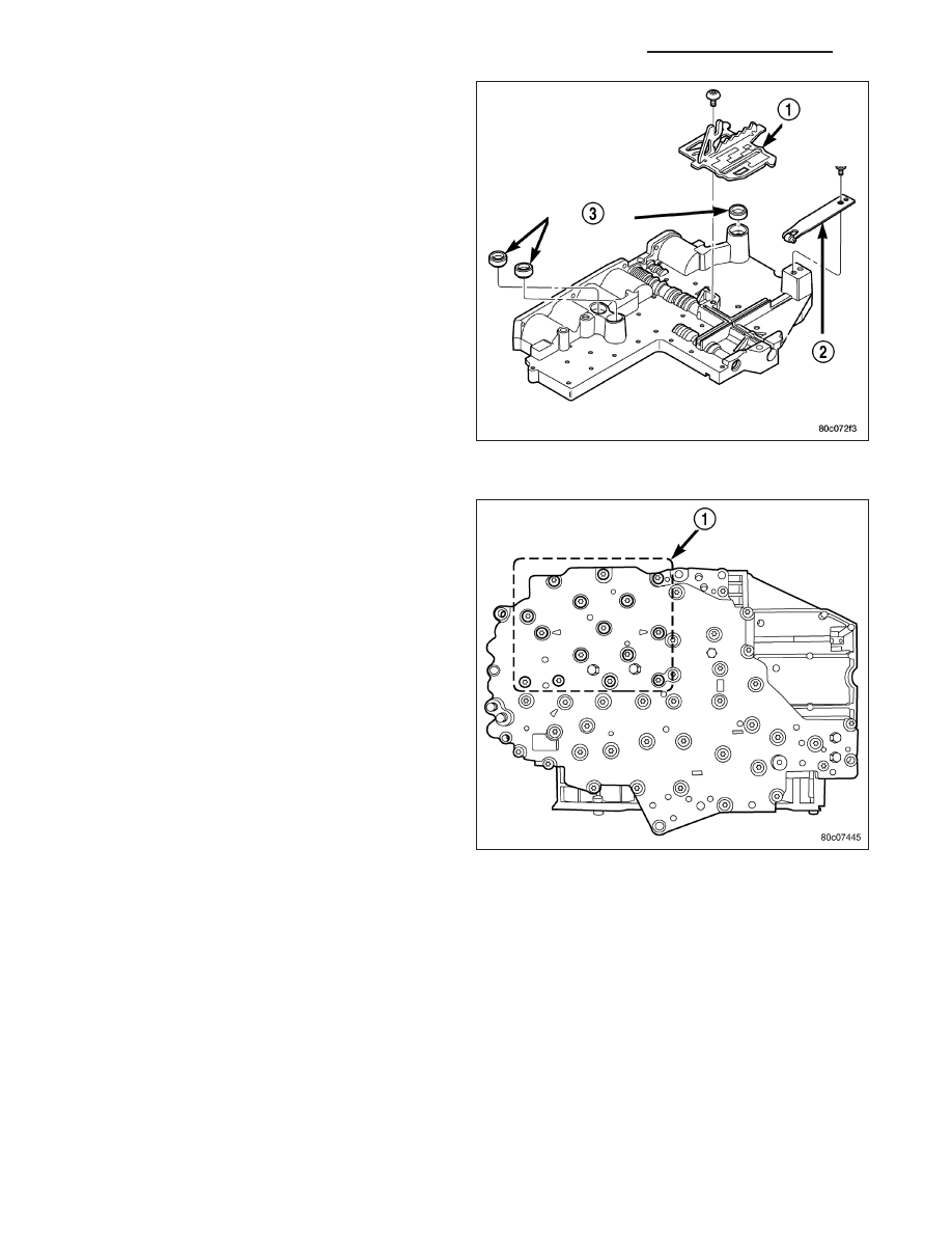
10. Install the TRS selector plate (1) onto the valve
body and the manual valve.
11. Position the detent spring (2) onto the valve body.
12. Install the screw to hold the detent spring (2) onto
the valve body. Tighten the screw to 4.5 N·m (40
in. lbs.).
13. Install new clutch passage seals (3) onto the
valve body, if necessary.
14. Install the solenoid and pressure switch assembly
onto the valve body.
15. Install the bolts (1) to hold the solenoid and pres-
sure switch assembly onto the valve body. Tighten
the bolts to 5.7 N·m (50 in. lbs.). Tighten the bolts
adjacent to the arrows cast into the bottom of the
transfer plate first.
21 - 824
AUTOMATIC TRANSMISSION 545RFE - SERVICE INFORMATION
ND

INSTALLATION
1. Check condition of seals on valve body and the
solenoid and pressure switch assembly. Replace
seals if cut or worn.
2. Place TRS selector plate in the PARK position.
3. Place the transmission in the PARK position.
4. Lubricate seal on the solenoid and pressure switch
assembly connector with petroleum jelly.
5. Position valve body in transmission and align the
manual lever on the valve body to the pin on the
transmission manual shift lever.
6. Seat valve body in case and install one or two
bolts to hold valve body in place.
7. Tighten valve body bolts alternately and evenly to
12 N·m (105 in. lbs.) torque.
CAUTION: The primary oil filter seal MUST be fully
installed flush against the oil pump body. DO NOT
install the seal onto the filter neck and attempt to
install the filter and seal as an assembly. Damage
to the transmission will result.
8. Install a new primary oil filter seal in the oil pump
inlet bore. Seat the seal in the bore with the butt
end of a hammer, or other suitable tool.
9. Place replacement filter (1) in position on valve
body and into the oil pump.
10. Install screw to hold filter to valve body. Tighten
screw to 4.5 N·m (40 in. lbs.) torque.
11. Connect the solenoid and pressure switch assem-
bly connector.
12. Install oil pan. Tighten pan bolts to 12 N·m (105 in. lbs.) torque.
13. Lower vehicle and fill transmission with Mopar
T
ATF +4.
14. Check and adjust gearshift cable, if necessary.
ND
AUTOMATIC TRANSMISSION 545RFE - SERVICE INFORMATION
21 - 825
TRANSFER CASE - ELECTRICAL DIAGNOSTICS
TABLE OF CONTENTS
page
page
TRANSFER CASE - ELECTRICAL
DIAGNOSTICS
DIAGNOSIS AND TESTING
TRANSFER CASE VERIFICATION TEST
VER 1 . . . . . . . . . . . . . . . . . . . . . . . . . . . . . 827
C1401- TRANSFER CASE RANGE SELECT
SWITCH CIRCUIT LOW . . . . . . . . . . . . . . . . 828
C1402- TRANSFER CASE RANGE SELECT
SWITCH CIRCUIT HIGH . . . . . . . . . . . . . . . . 833
POSITION SENSOR CIRCUIT LOW . . . . . . . 838
POSITION SENSOR CIRCUIT HIGH . . . . . . . 843
CONTROL CIRCUIT LOW . . . . . . . . . . . . . . 849
CONTROL CIRCUIT HIGH . . . . . . . . . . . . . . 858
C230A- NEUTRAL INDICATOR CONTROL
CIRCUIT LOW . . . . . . . . . . . . . . . . . . . . . . . 866
C230B- NEUTRAL INDICATOR CONTROL
CIRCUIT HIGH . . . . . . . . . . . . . . . . . . . . . . . 870
TRANSFER CASE - ELECTRICAL DIAGNOSTICS
DIAGNOSIS AND TESTING
21 - 826
TRANSFER CASE - ELECTRICAL DIAGNOSTICS
ND
TRANSFER CASE VERIFICATION TEST VER 1
Diagnostic Test
1.
TRANSFER CASE VERIFICATION TEST— VER 1
Disconnect all jumper wires and reconnect all previously disconnected components and connectors.
With the scan tool, select Clear Stored DTCs.
Make sure that all accessories are turned off and that the battery is fully charged.
Test drive the vehicle in each Transfer Case range and verify proper operation in each range.
NOTE: To select or deselect 2WD, AWD or 4HI mode, vehicle speed must be below 55 M.P.H. (88 KM/H) with
all wheels at vehicle speed.
NOTE: Shifts will not take place with a wheel speed difference of greater than 13 M.P.H. between the front
and rear wheels.
NOTE: To select or deselect 4LO (if equipped), vehicle speed must be below 3 M.P.H. (5 KM/H) with the
ignition ON and the transmission in neutral (auto trans) or the clutch pedal pressed (man trans).
NOTE: To select or deselect Transfer Case Neutral, vehicle speed must be 0 M.P.H. with the ignition ON,
engine OFF, the brake pedal applied, and the transmission in neutral (auto trans) or the clutch pedal
pressed (man trans). Press the Neutral button (if equipped) on the Transfer Case Selector Switch until the
Neutral Indicator is illuminated.
WARNING: Apply the parking brake. The vehicle may roll with the Transfer Case in neutral.
NOTE: To verify that the Transfer Case is in Neutral, shift the automatic transmission into reverse and
release the brake pedal for three seconds or shift the manual transmission into gear and slowly release the
clutch pedal. There should be no vehicle movement if the Transfer Case is in Neutral.
With the scan tool, select View DTCs in the Front Control Module (FCM) and in the Cluster (CCN).
Are there any DTCs present in the Front Control Module (FCM) or in the Cluster (CCN)?
Yes
>> Return to the symptom list and perform the appropriate diagnostic test.
No
>> Repair is complete.
ND
TRANSFER CASE - ELECTRICAL DIAGNOSTICS
21 - 827
Нет комментариевНе стесняйтесь поделиться с нами вашим ценным мнением.
Текст