Dodge Dakota (ND). Manual — part 742
P0516-BATTERY TEMPERATURE SENSOR CIRCUIT LOW (CONTINUED)
3.
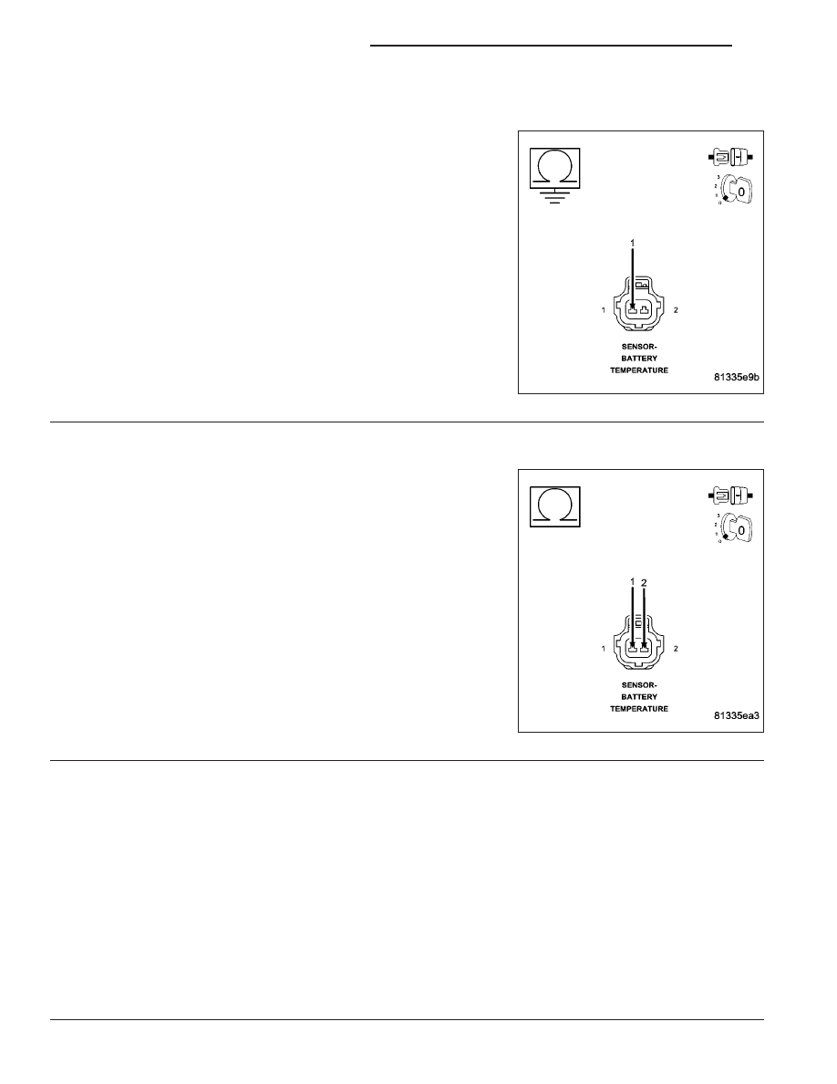
(K25) BATT TEMP SIGNAL CIRCUIT SHORTED TO GROUND
Turn the ignition off.
Disconnect the C1 FCM harness connector.
Measure the resistance between ground and the (K25) Batt Temp Sig-
nal circuit in the Battery Temp Sensor harness connector.
Is the resistance below 100 ohms?
Yes
>> Repair the short to ground in the (K25) Batt Temp Signal
circuit.
Perform POWERTRAIN VERIFICATION TEST. (Refer to 9
- ENGINE - STANDARD PROCEDURE)
No
>> Go To 4
4.
(K25) BATT TEMP SIGNAL CIRCUIT SHORTED TO THE (K91) BATT TEMP RETURN CIRCUIT
Measure the resistance between the (K25) Batt Temp Signal circuit
and the (K91) Batt Temp Return circuit in the Battery Temp Sensor
harness connector.
Is the resistance below 5.0 ohms?
Yes
>> Repair the short between the (K91) Batt Temp Return cir-
cuit and the (K25) Batt Temp Signal circuit.
Perform POWERTRAIN VERIFICATION TEST. (Refer to 9
- ENGINE - STANDARD PROCEDURE)
No
>> Go To 5
5.
FRONT CONTROL MODULE
NOTE: Before continuing, check the FCM harness connector terminals for corrosion, damage, or terminal
push out. Repair as necessary.
Using the schematics as a guide, inspect the wire harness and connectors. Pay particular attention to all Power and
Ground circuits.
Were there any problems found?
Yes
>> Repair as necessary.
Perform BODY VERIFICATION TEST-VER 1. (Refer to 8 - ELECTRICAL/ELECTRONIC CONTROL
MODULES/FRONT CONTROL MODULE - DIAGNOSIS AND TESTING)
No
>> Replace and program the Front Control Module per Service Information.
Perform BODY VERIFICATION TEST-VER 1. (Refer to 8 - ELECTRICAL/ELECTRONIC CONTROL
MODULES/FRONT CONTROL MODULE - DIAGNOSIS AND TESTING)
9 - 506
ENGINE ELECTRICAL DIAGNOSTICS
ND
P0517-BATTERY TEMPERATURE SENSOR CIRCUIT HIGH
ND
ENGINE ELECTRICAL DIAGNOSTICS
9 - 507
P0517-BATTERY TEMPERATURE SENSOR CIRCUIT HIGH (CONTINUED)
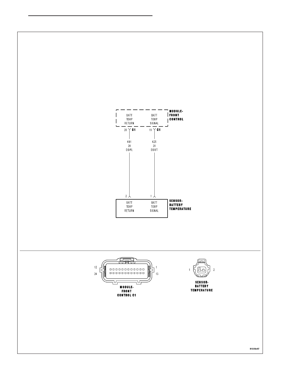
For the Engine circuit diagram (Refer to 9 - ENGINE - SCHEMATICS AND DIAGRAMS).
For a complete wiring diagram Refer to Section 8W.
•
When Monitored:
Ignition on and battery voltage greater than 10 volts.
•
Set Condition:
Battery temperature voltage above 4.94 volts. One Trip Fault. Three good trips to turn off the MIL.
Possible Causes
(K25) BATT TEMP SENSOR SIGNAL CIRCUIT SHORTED TO BATTERY VOLTAGE
(K25) BATT TEMP SIGNAL CIRCUIT OPEN
(K91) BATT TEMP RETURN CIRCUIT OPEN
BATTERY TEMPERATURE SENSOR
FRONT CONTROL MODULE
Always perform the Pre-Diagnostic Troubleshooting procedure before proceeding. (Refer to 9 - ENGINE -
DIAGNOSIS AND TESTING).
Diagnostic Test
1.
BATTERY TEMPERATURE SENSOR VOLTAGE ABOVE 4.8 VOLTS
NOTE: Diagnose any CAN - C Communication DTCs before continuing.
Ignition on, engine not running.
With a scan tool, monitor the Battery Temperature Sensor voltage.
Is the voltage above 4.9 volts?
Yes
>> Go To 2
No
>> Refer to the INTERMITTENT CONDITION Diagnostic Procedure.
Perform POWERTRAIN VERIFICATION TEST. (Refer to 9 - ENGINE - STANDARD PROCEDURE)
2.
BATTERY TEMPERATURE SENSOR
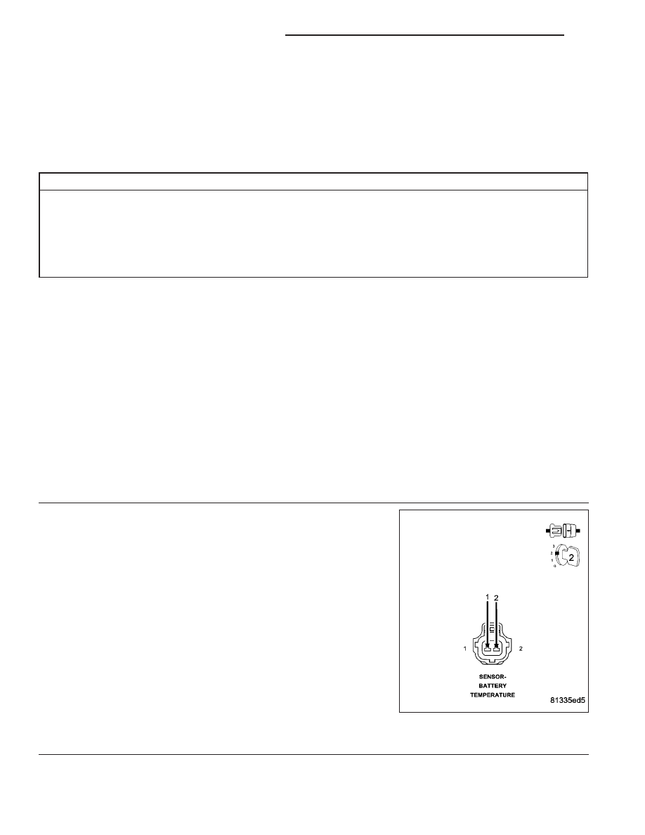
Turn the ignition off.
Disconnect the Battery Temperature Sensor harness connector.
Ignition on, engine not running.
With the scan tool, read the Battery Temp Voltage value.
Connect a jumper wire between the (K25) Batt Temp Signal circuit and
the (K91) Batt Temp Return circuit in the Battery Temp Sensor harness
connector.
Did the Battery Temp voltage value change from greater than
4.5 volts to less than 1.0 volt with the jumper wire installed?
Yes
>> Replace the Battery Temperature Sensor.
Perform POWERTRAIN VERIFICATION TEST. (Refer to 9
- ENGINE - STANDARD PROCEDURE)
No
>> Go To 3
NOTE: Remove the jumper wire before continuing.
9 - 508
ENGINE ELECTRICAL DIAGNOSTICS
ND
P0517-BATTERY TEMPERATURE SENSOR CIRCUIT HIGH (CONTINUED)
3.
(K25) BATT TEMP SIGNAL CIRCUIT SHORTED TO BATTERY VOLTAGE
Turn the ignition off.
Disconnect the C1 FCM harness connector.
Measure the voltage on the (K25) Batt Temp Signal circuit in the Bat-
tery Temp Sensor harness connector.
Is the voltage above 0 volts?
Yes
>> Repair the short to battery voltage in the (K25) Batt Temp
Signal circuit.
Perform POWERTRAIN VERIFICATION TEST. (Refer to 9
- ENGINE - STANDARD PROCEDURE)
No
>> Go To 4
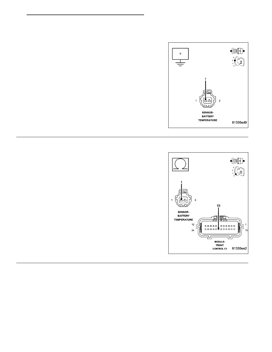
4.
(K25) BATT TEMP SIGNAL CIRCUIT OPEN
Turn the ignition off.
Measure the resistance of the (K25) Batt Temp Signal circuit from the
Battery Temp Sensor harness connector to the C6 IPM harness con-
nector.
Is the resistance below 5.0 ohms?
Yes
>> Go To 5
No
>> Repair the open in the (K25) Batt Temp Signal circuit.
Perform POWERTRAIN VERIFICATION TEST. (Refer to 9
- ENGINE - STANDARD PROCEDURE)
ND
ENGINE ELECTRICAL DIAGNOSTICS
9 - 509
Нет комментариевНе стесняйтесь поделиться с нами вашим ценным мнением.
Текст