Dodge Dakota (ND). Manual — part 773
P2074-MAP/TPS CORRELLATION - HIGH AIRFLOW/VACUUM LEAK DETECTED (CONTINUED)
7.
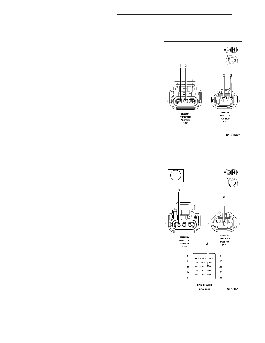
THROTTLE POSITION SENSOR
Connect the C2 PCM harness connector.
Ignition on, engine not running.
With a scan tool, monitor the TP Sensor voltage.
Connect a jumper wire between the (K22) TP Sensor No.1 Signal cir-
cuit and the (K900) Sensor ground circuit in the Sensor harness con-
nector.
Does the TP Sensor voltage change from approximately 4.9
volts to below 0.5 of a volt with the jumper wire installed?
Yes
>> Replace the Throttle Position Sensor.
Perform the POWERTRAIN VERIFICATION TEST. (Refer
to 9 - ENGINE - STANDARD PROCEDURE)
No
>> Go To 8
NOTE: Remove the jumper wire before continuing.
8.
EXCESSIVE RESISTANCE IN THE (K22) TP NO.1 SIGNAL CIRCUIT
Turn the ignition off.
Disconnect the C2 PCM harness connector.
CAUTION: Do not probe the PCM harness connectors. Probing
the PCM harness connectors will damage the PCM terminals
resulting in poor terminal to pin connection. Install Miller Special
Tool #8815 to perform diagnosis.
Measure the resistance of the (K22) TP Sensor No.1 Signal circuit
from the TP Sensor harness connector to the appropriate terminal of
special tool #8815.
Is the resistance below 5.0 ohms?
Yes
>> Go To 9
No
>> Repair the excessive resistance in the (K22) TP Sensor
No.1 Signal circuit.
Perform the POWERTRAIN VERIFICATION TEST. (Refer
to 9 - ENGINE - STANDARD PROCEDURE)
9 - 630
ENGINE ELECTRICAL DIAGNOSTICS
ND
P2074-MAP/TPS CORRELLATION - HIGH AIRFLOW/VACUUM LEAK DETECTED (CONTINUED)
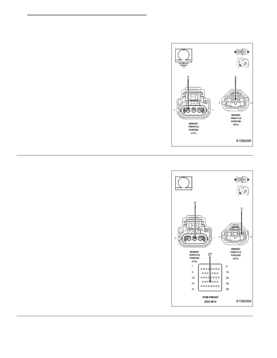
9.
(K22) TP SENSOR NO.1 SIGNAL CIRCUIT SHORTED TO GROUND
Measure the resistance between ground and the (K22) TP Sensor
No.1 Signal circuit in the TP Sensor harness connector.
Is the resistance below 100 ohms?
Yes
>> Repair the short to ground in the (K22) TP Sensor No.1
Signal circuit.
Perform the POWERTRAIN VERIFICATION TEST. (Refer
to 9 - ENGINE - STANDARD PROCEDURE
No
>>
Go To 10
10.
EXCESSIVE RESISTANCE IN THE (K900) SENSOR GROUND CIRCUIT
CAUTION: Do not probe the PCM harness connectors. Probing
the PCM harness connectors will damage the PCM terminals
resulting in poor terminal to pin connection. Install Miller Special
Tool #8815 to perform diagnosis.
Measure the resistance of the (K900) Sensor ground circuit from the
TP Sensor harness connector to the appropriate terminal of special
tool #8815.
Is the resistance below 5.0 ohms?
Yes
>> Go To 17
No
>> Repair the excessive resistance in the (K900) Sensor
ground circuit.
Perform the POWERTRAIN VERIFICATION TEST. (Refer
to 9 - ENGINE - STANDARD PROCEDURE)
ND
ENGINE ELECTRICAL DIAGNOSTICS
9 - 631
P2074-MAP/TPS CORRELLATION - HIGH AIRFLOW/VACUUM LEAK DETECTED (CONTINUED)
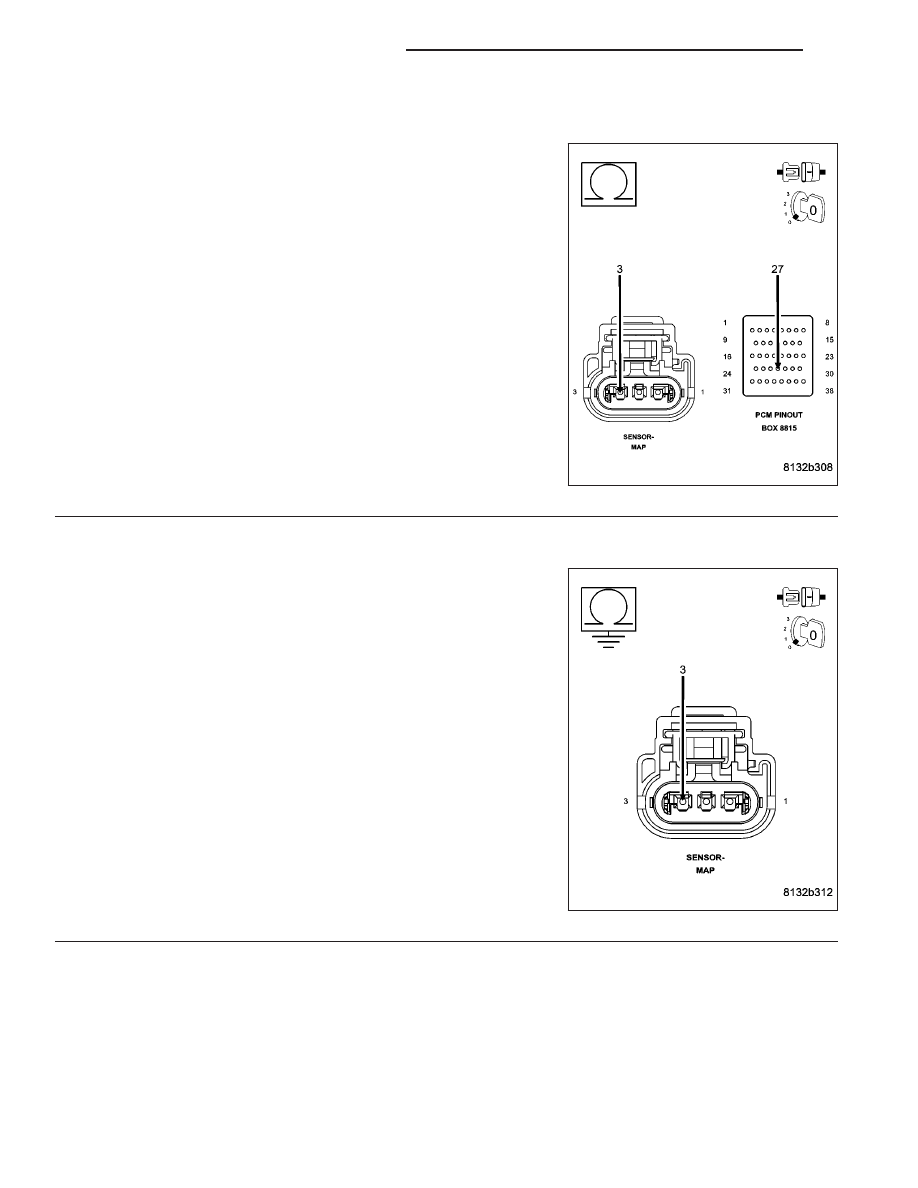
11.
EXCESSIVE RESISTANCE IN THE (F856) 5-VOLT SUPPLY CIRCUIT
Turn the ignition off.
Disconnect the MAP Sensor harness connector.
Disconnect the C1 PCM harness connector.
CAUTION: Do not probe the PCM harness connectors. Probing
the PCM harness connectors will damage the PCM terminals
resulting in poor terminal to pin connection. Install Miller Special
Tool #8815 to perform diagnosis.
Measure the resistance of the (F856) 5-volt Supply circuit from the
MAP Sensor harness connector to the appropriate terminal of special
tool #8815.
Is the resistance below 5.0 ohms?
Yes
>> Go To 12
No
>> Repair the excessive resistance in the (F856) 5-volt Sup-
ply circuit.
Perform the POWERTRAIN VERIFICATION TEST. (Refer
to 9 - ENGINE - STANDARD PROCEDURE)
12.
(F856) 5-VOLT SUPPLY CIRCUIT SHORTED TO GROUND
Measure the resistance between ground and the (F856) 5-volt Supply
circuit in the MAP Sensor harness connector.
Is the resistance above 100k ohms?
Yes
>> Go To 13
No
>> Repair the short to ground in the (F856) 5-volt Supply cir-
cuit.
Perform the POWERTRAIN VERIFICATION TEST. (Refer
to 9 - ENGINE - STANDARD PROCEDURE)
9 - 632
ENGINE ELECTRICAL DIAGNOSTICS
ND
P2074-MAP/TPS CORRELLATION - HIGH AIRFLOW/VACUUM LEAK DETECTED (CONTINUED)
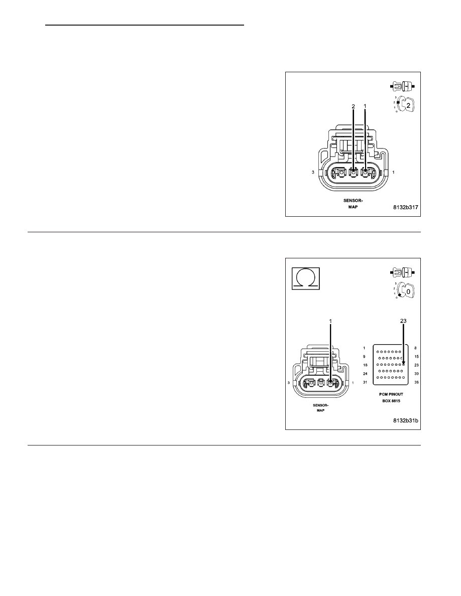
13.
MAP SENSOR
Turn the ignition off.
Connect the C1 PCM harness connector.
Ignition on, engine not running.
With a scan tool, monitor the MAP Sensor voltage.
Connect a jumper wire between the (K1) MAP Signal circuit and the
(K900) Sensor ground circuit.
Does the scan tool display MAP voltage from approximately 4.9
volts to below 0.5 of a volt with the jumper wire installed?
Yes
>> Replace the MAP Sensor.
Perform the POWERTRAIN VERIFICATION TEST. (Refer
to 9 - ENGINE - STANDARD PROCEDURE)
No
>> Go To 14
NOTE: Remove the jumper wire before continuing.
14.
EXCESSIVE RESISTANCE IN THE (K1) MAP SIGNAL CIRCUIT
Turn the ignition off.
Disconnect the C2 PCM harness connector.
CAUTION: Do not probe the PCM harness connectors. Probing
the PCM harness connectors will damage the PCM terminals
resulting in poor terminal to pin connection. Install Miller Special
Tool #8815 to perform diagnosis.
Measure the resistance of the (K1) MAP Signal circuit from the MAP
Sensor harness connector to the appropriate terminal of special tool
#8815.
Is the resistance below 5.0 ohms?
Yes
>> Go To 15
No
>> Repair the excessive resistance in the (K1) MAP Signal
circuit
Perform the POWERTRAIN VERIFICATION TEST. (Refer
to 9 - ENGINE - STANDARD PROCEDURE)
ND
ENGINE ELECTRICAL DIAGNOSTICS
9 - 633
Нет комментариевНе стесняйтесь поделиться с нами вашим ценным мнением.
Текст