Dodge Dakota (ND). Manual — part 430

B2102-IGNITION RUN/START INPUT CIRCUIT HIGH (CONTINUED)
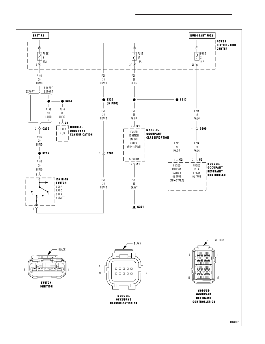
For the Occupant Classification System circuit diagram (Refer to 8 - ELECTRICAL/RESTRAINTS - SCHEMATICS
AND DIAGRAMS).
For a complete wiring diagram Refer to Section 8W.
•
When Monitored:
While the CAN bus ignition status is RUN or missing and the IOD status is
9
IN
9
. The module checks the (F201)
Fused Ignition Switch Output (Run-Start) circuit voltage input range.
•
Set Condition:
If the module detects that the ignition voltage is greater than 24.25 volts ±0.25 volts for 10 seconds.
Possible Causes
VEHICLE CHARGING SYSTEM
VEHICLE WIRING & HARNESS CONNECTORS
OCCUPANT RESTRAINT CONTROLLER
Diagnostic Test
1.
VERIFY THAT DTC B2102-IGNITION RUN/START INPUT CIRCUIT HIGH IS ACTIVE
NOTE: Ensure the battery is fully charged.
NOTE: When reconnecting Airbag system components, the ignition must be turned off and the battery must
be disconnected.
Turn the ignition on, then off, and then on again.
With the scan tool, read Occupant Classification Module (OCM) DTCs.
Does the scan tool display active: B2102-IGNITION RUN/START INPUT CIRCUIT HIGH?
Yes
>> Go To 2
No
>> Go To 3
2.
CHECK FOR CHARGING SYSTEM RELATED DTCs IN THE POWERTRAIN CONTROL MODULE (PCM)
With the scan tool in ECU View, select PCM and check for any Charging System related DTCs.
Does the scan tool display any Charging System related DTCs?
Yes
>> Diagnose and repair the DTCs. Refer to (Refer to 9 - ENGINE - DIAGNOSIS AND TESTING).
No
>> Replace the ORC in accordance with the Service Information.
Perform OCS VERIFICATION TEST - VER 1.
8O - 316
RESTRAINTS - ELECTRICAL DIAGNOSTICS
ND
B2102-IGNITION RUN/START INPUT CIRCUIT HIGH (CONTINUED)
3.
TEST FOR INTERMITTENT CONDITION
With the scan tool, record and erase all DTCs from all Airbag modules.
If any ACTIVE codes are present they must be resolved before diagnosing any stored codes.
WARNING: To avoid personal injury or death, turn the ignition off, disconnect the battery and wait two min-
utes before proceeding.
Using the wiring diagram/schematic as a guide, inspect the wiring and connectors.
Look for chaffed, pierced, pinched, or partially broken wires and broken, bent, pushed out, spread, corroded, or
contaminated terminals.
The following additional checks may assist you in identifying a possible intermittent problem.
Reconnect any disconnected components and harness connector.
WARNING: To avoid personal injury or death, turn the ignition on, then reconnect the battery.
With the scan tool, monitor active codes as you work through the following steps.
WARNING: To avoid personal injury or death, maintain a safe distance from all airbags while performing the
following steps.
Wiggle the wiring harness and connectors of the related airbag circuit or component.
If codes are related to the Driver Airbag circuits, rotate the steering wheel from stop to stop.
If only stored codes return, continue the test until the problem area has been isolated.
In the previous steps you have attempted to recreate the conditions responsible for setting the active DTC in ques-
tion.
Does the scan tool display any ACTIVE DTCs?
Yes
>> Select appropriate symptom from Symptom List.
No
>> No problem found Erase all codes before returning vehicle to customer.
ND
RESTRAINTS - ELECTRICAL DIAGNOSTICS
8O - 317
B210D-BATTERY VOLTAGE LOW
8O - 318
RESTRAINTS - ELECTRICAL DIAGNOSTICS
ND

B210D-BATTERY VOLTAGE LOW (CONTINUED)
For the Occupant Classification System circuit diagram (Refer to 8 - ELECTRICAL/RESTRAINTS - SCHEMATICS
AND DIAGRAMS).
For a complete wiring diagram Refer to Section 8W.
•
When Monitored:
OCM-While the CAN bus ignition status received is RUN or missing, the module checks the (A956) Fused B+
circuit voltage input range and the (F201) Fused Ignition Switch Output Run Only circuit voltage input range.
•
Set Condition:
OCM-If the module detects that the battery voltage is less than or equal to 6.25 volts ±0.25 volts.
•
When Monitored:
ORC-While the CAN bus ignition status received is RUN or missing, the module checks the (F201) Fused
Ignition Switch Output (RUN/START) circuit and the (F100) Fused Run Relay Output (RUN ONLY) circuit volt-
age input range.
•
Set Condition:
ORC-If the module detects that the battery voltage is less than or equal to 6.25 volts ±0.25 volts on either the
F201 or F100 circuits.
Possible Causes
OCM (A956) FUSED B(+) CIRCUIT
ORC (F201) FUSED IGNITION SWITCH OUTPUT (RUN/START) CIRCUIT OPEN
ORC (F100) FUSED IGNITION SWITCH RUN OUTPUT CIRCUIT OPEN
VEHICLE CHARGING SYSTEM
OCCUPANT CLASSIFICATION MODULE
OCCUPANT RESTRAINT CONTROLLER
Diagnostic Test
1.
CHECK FOR AN ACTIVE DTC
NOTE: Ensure the battery is fully charged.
NOTE: Troubleshoot any PCM charging/cranking DTCs before proceeding.
NOTE: When reconnecting Airbag system components, the ignition must be turned off and the battery must
be disconnected.
Turn the ignition on.
With the scan tool, read Occupant Restraint Controller (ORC) DTCs.
Select module and DTC type.
OCM Active
Go To 2
OCM Stored
Go To 4
ORC Active
Go To 3
ORC Stored
Go To 4
ND
RESTRAINTS - ELECTRICAL DIAGNOSTICS
8O - 319
Нет комментариевНе стесняйтесь поделиться с нами вашим ценным мнением.
Текст